Eureka AIR delivers breakthrough ideas for toughest innovation challenges, trusted by R&D personnel around the world.

Control device and method for a diesel engine and diesel engine

Inactive Publication Date: 2004-08-31
MITSUBISHI MOTORS CORP
View PDF12 Cites 23 Cited by
  • Summary
  • Abstract
  • Description
  • Claims
  • Application Information

AI Technical Summary

Benefits of technology

It is an object of the present invention to provide a diesel engine that can reduce both of smoke and NO.sub.x by increasing an upper limit value of EGR ratio for suppressing emission of smoke while preventing oil dilution or increase in HC or CO from occurring.
In this case, since the fuel injection timing is set up at an advance side from the injection timing when the smoke emission characteristic indicates an increasing tendency and then a decreasing tendency for an increase in the EGR ratio, the range of the EGR ratio to maintain the smoke emission amount at a low level can be extended. Moreover, since the operation of the EGR ratio adjusting means is controlled so that the excess air ratio maybe 1.0 or less, the EGR ratio can be increased without worrying about the smoke emission amount to discharge and reduce NO.sub.x from the NO.sub.x occluded catalyst efficiently.

Problems solved by technology

In this case, if the excess air ratio is changed with the EGR ratio, the smoke emission amount is over the peak, whereby it is impossible to avoid a rapid transient increase of the smoke emission amount.

Method used


Image

  • Control device and method for a diesel engine and diesel engine
  • Control device and method for a diesel engine and diesel engine
  • Control device and method for a diesel engine and diesel engine

Examples


first embodiment

The present invention will be described below in connection with a diesel engine of the common rail system.

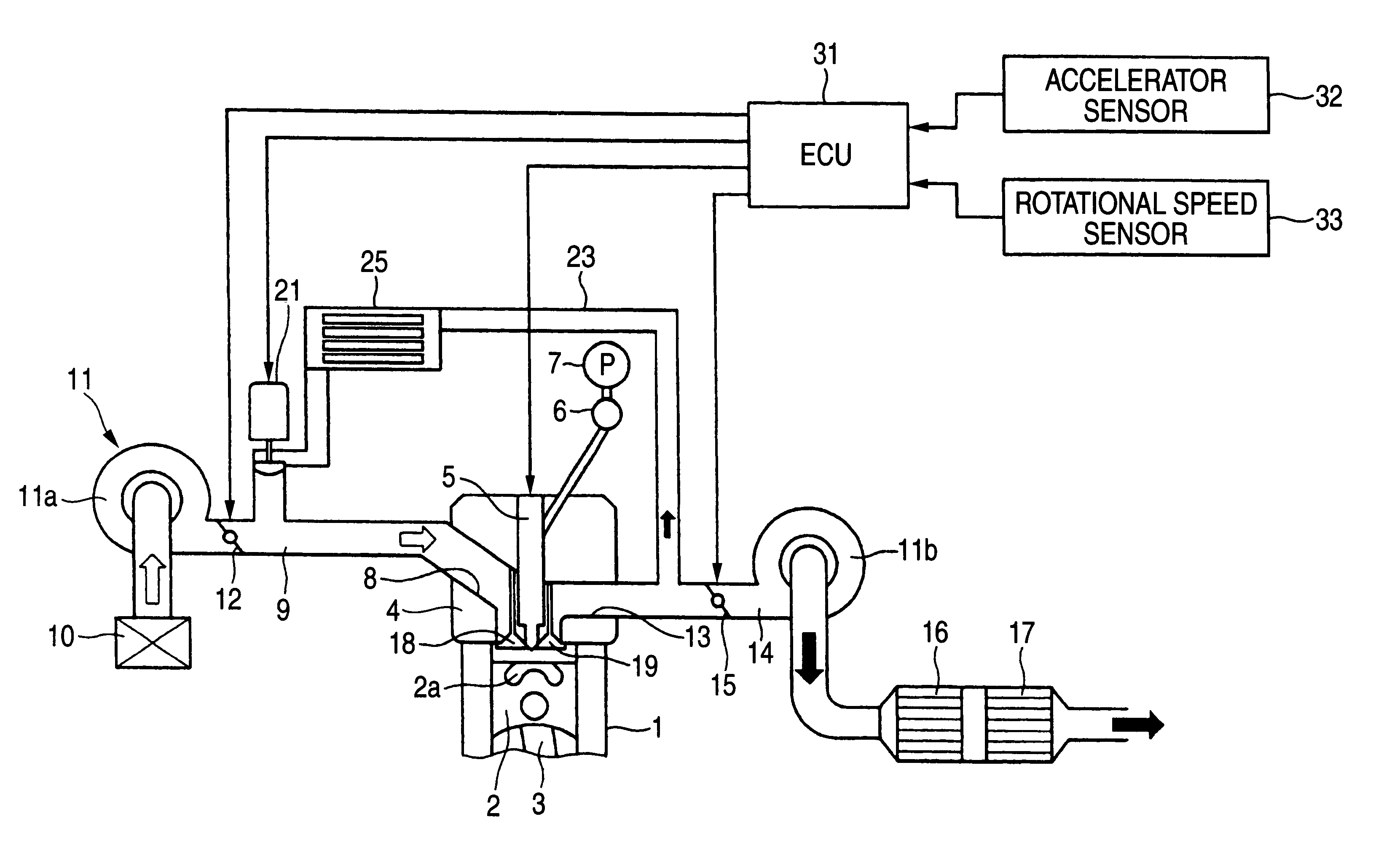
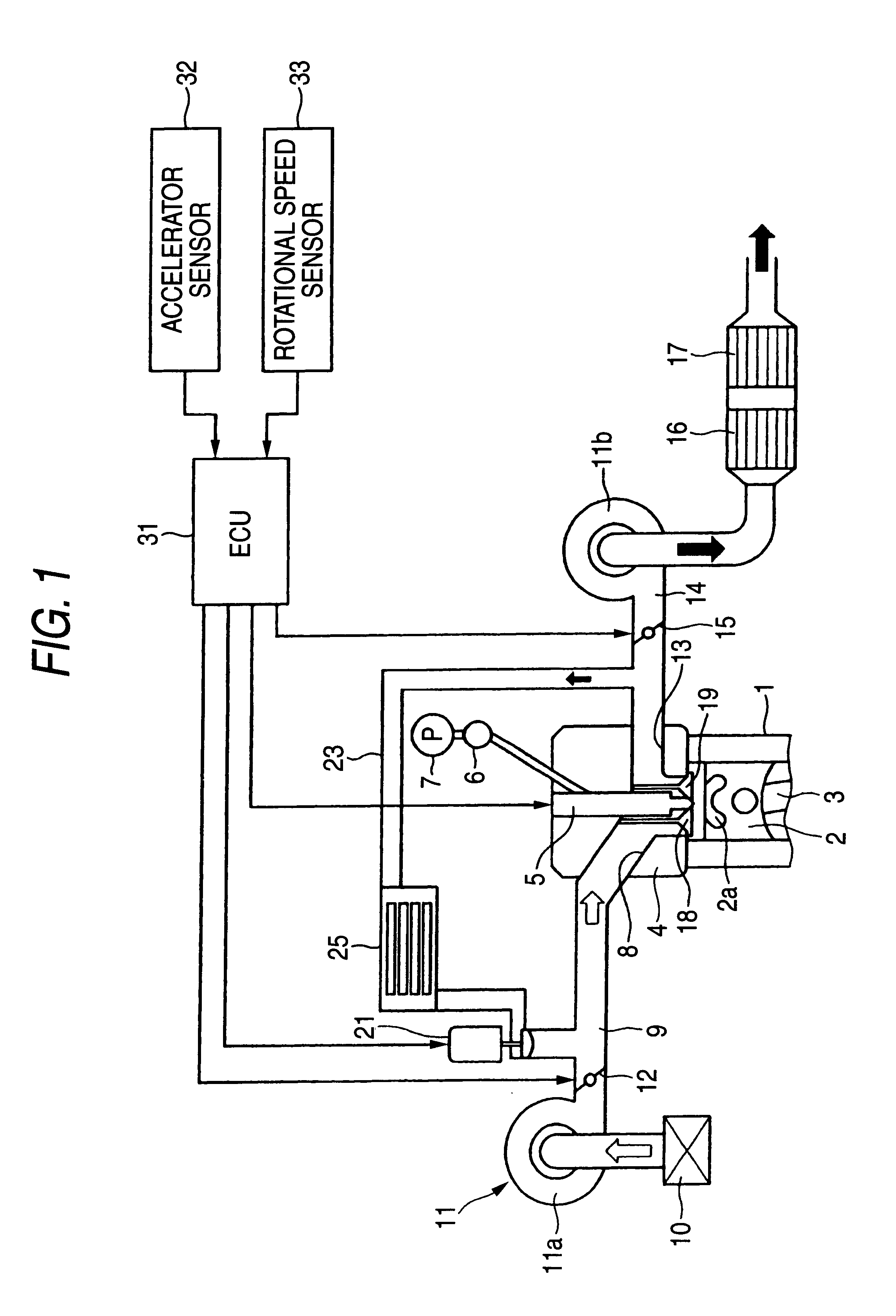
FIG. 1 is an overall constitutional view of the diesel engine according to the first embodiment. In FIG. 1, one-cylinder of the diesel engine is represented, in which a piston 2 disposed within a cylinder block 1 is connected via a connecting rod 3 to a crankshaft (not shown). In a cylinder head 4 of the engine, a fuel injection valve 5 is disposed to be confronted into the cylinder, and connected to a common rail 6 that is common to each cylinder. A fuel pump 7 is connected to the common rail 6 so that a high pressure fuel supplied from the fuel pump 7 is reserved within the common rail 6.

The fuel injection valve 5 is opened at a predetermined timing near the top dead center of compression, so that a high pressure fuel within the common rail 6 is injected from the fuel injection valve 5 to a cavity 2a in the head portion of the piston, ignited and combusted in the compressed a...

second embodiment

A second embodiment of the diesel engine embodying the present invention will be described below. The diesel engine of this embodiment is different from that of the first embodiment, in that a process of purging NOx occluded into the NO.sub.x catalyst 16 is additionally provided. Other parts are common. Hence, the description for the common parts is omitted, and different points are mainly explained.

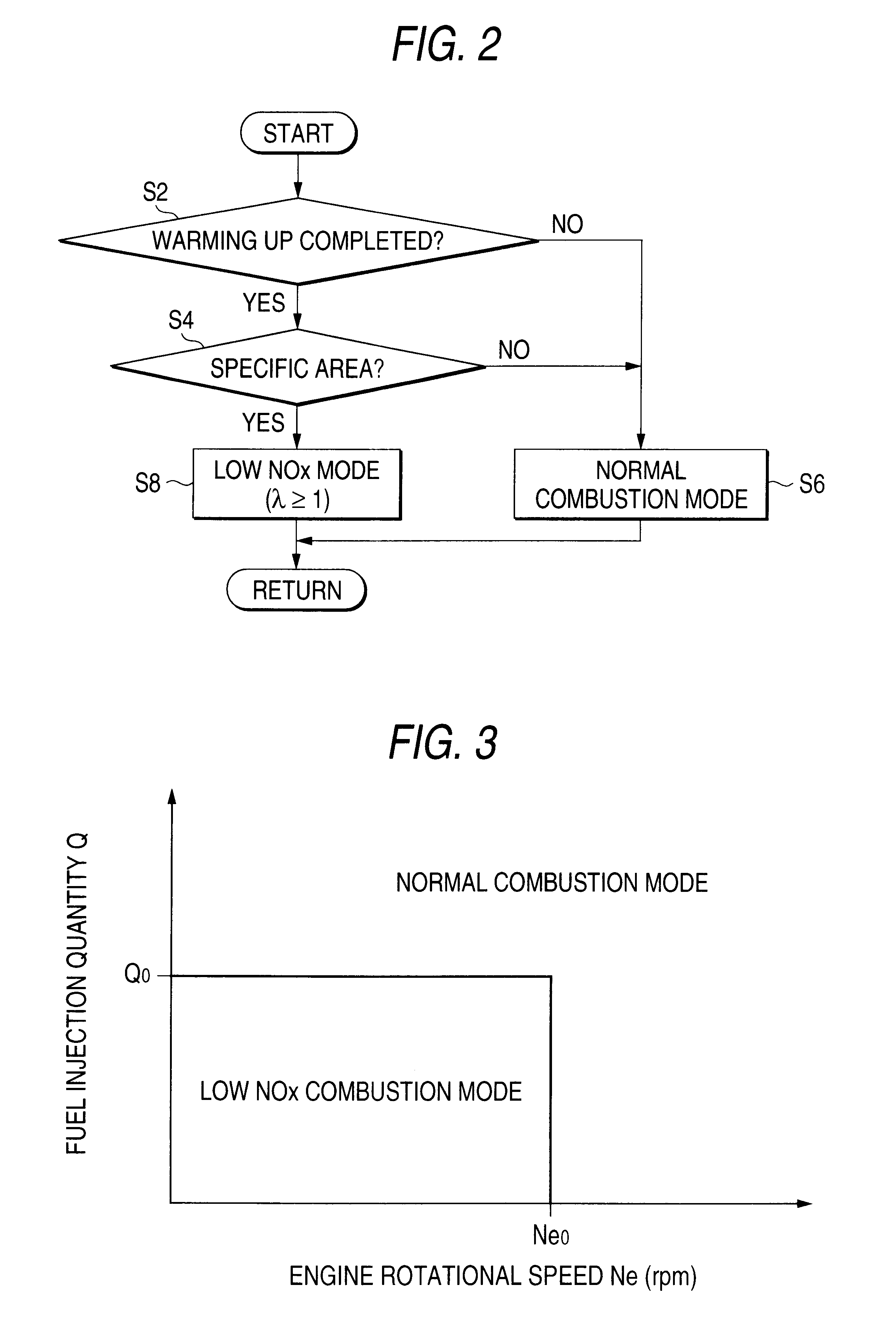
In the low NO.sub.x combustion mode, the NO.sub.x emission is reduced, but the complete exhaust suppression is difficult. On the other hand, in the normal combustion mode, the NO.sub.x exhaust characteristics of the typical diesel engine are attained, whereby the exhausted NO.sub.x is occluded into the NO.sub.x catalyst 16, and prevented from being exhausted into the atmosphere. Thus, when the low NO.sub.x combustion mode is executed, the process of discharging and reducing NO.sub.x occluded into the NO.sub.x catalyst 16 is required. In this embodiment, NO.sub.x is purged by executing an...


PUM


Abstract

A low NO.sub.x combustion mode is executed in which the fuel injected timing IT is greatly advanced to 36.degree. BTDC as compared with a normal value of roughly 10.degree. BTDC. At this fuel injection timing IT, the smoke emission amount is suppressed below an extremely low value, even if the EGR ratio Regr is increased to about 56%, and the NO.sub.x emission amount is suppressed owing to a large amount of EGR, so that the smoke and NO.sub.x can be reduced at the same time.

Description

BACKGROUND OF THE INVENTION1. Field of the InventionThe present invention relates to a diesel engine, particularly to a control of fuel injection timing and EGR recirculation quantity.2. Description of the Related ArtIn a diesel engine that performs a lean operation mainly caused by diffusion combustion, NO.sub.x is likely to occur by a high excess air ratio. As its countermeasure, an EGR control is used in which a part of exhaust gas is recirculationed into an intake air system and a combustion temperature is decreased to suppress the generation of NO.sub.x. Though the NO.sub.x suppression effect is enhanced along with an increased EGR ratio, in the diffusion combustion in which combustion is caused on a combustible gas mixture layer at the boundary between injection fuel and compressed air, a cinder of fuel occurs if the EGR ratio is excessively increased, resulting in a problem that the smoke emission amount is rapidly increased. Therefore, to avoid this problem, the EGR ratio ha...

Claims


Application Information

Patent Timeline
IPC IPC(8): F02D41/00F02D41/02F02D21/00F02D21/08F02D41/40F02D9/04F02D41/30F02D9/00F02M25/07F01N3/08F02D23/02F02D23/00F02B1/12F02B3/00F02B1/00F02B3/06F02D41/04F02D43/00F02D45/00
CPCF01N3/0842F02D9/04F02D41/0057F02D41/0275F02D41/3035F02D41/3064F02D41/401F02M25/0727F02M25/0782F02B1/12F02B3/06F02B2275/14F02D23/02F02D2250/11F02M25/0707F02M25/0738Y02T10/44Y02T10/123Y02T10/47F02M26/05F02M26/23F02M26/33F02M26/615Y02T10/12Y02T10/40F02D41/40
Inventor SHIGAHARA, KEIHATA, MICHIHIROMORITA, TOSHINORIKOGA, NORIYUKIYANAGAWA, YUJI
Owner MITSUBISHI MOTORS CORP
Why Eureka
Eureka Blog
Learn More