Eureka AIR delivers breakthrough ideas for toughest innovation challenges, trusted by R&D personnel around the world.

Methods and apparatus for acquiring a swiped fingerprint image

Active Publication Date: 2005-11-03
SYNAPTICS INC
View PDF99 Cites 109 Cited by
  • Summary
  • Abstract
  • Description
  • Claims
  • Application Information

AI Technical Summary

Benefits of technology

[0009] The position of the user's finger may be sensed with a finger position sensor. An angle of the user's finger relative to the sensor may be determined from start and end positions of the user's finger on the sensor. The angle of the user's finger relative to the finger position sensor may be displayed to assist the user in moving to the desired finger placement.

Problems solved by technology

Training a user to properly swipe his or her finger across the image sensor remains an impediment to adoption of these devices.

Method used


Image

  • Methods and apparatus for acquiring a swiped fingerprint image
  • Methods and apparatus for acquiring a swiped fingerprint image
  • Methods and apparatus for acquiring a swiped fingerprint image

Examples


first embodiment

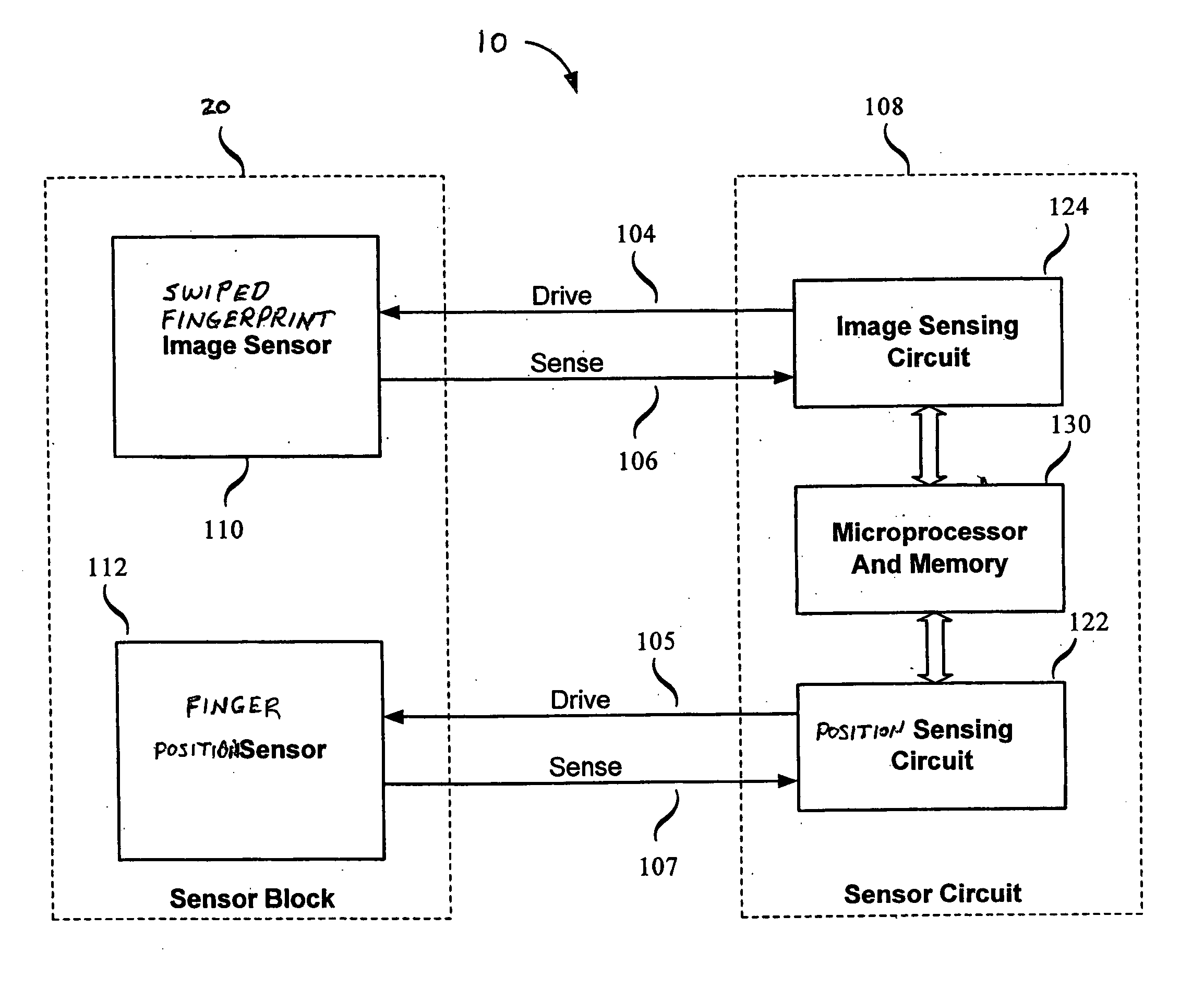
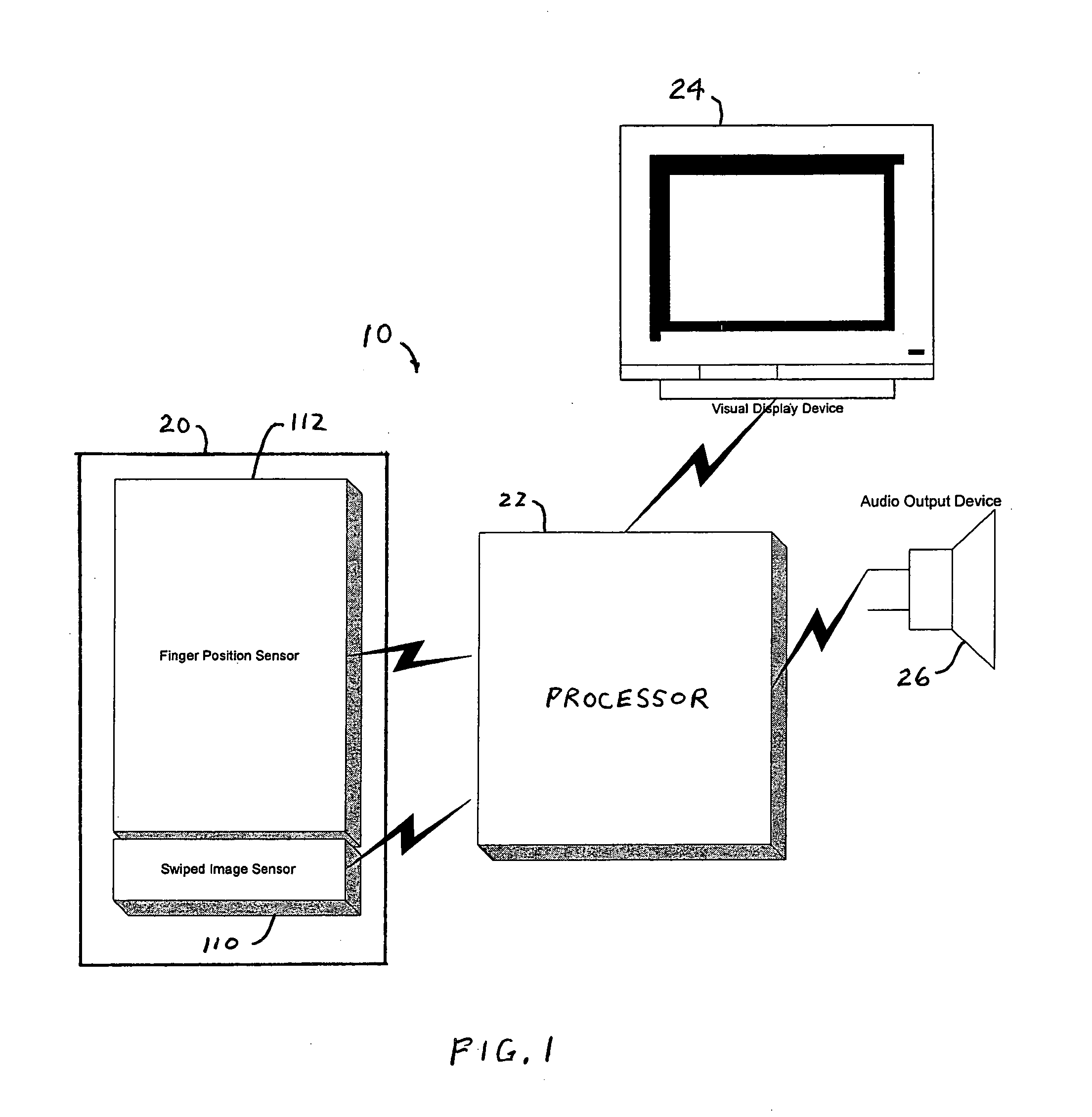
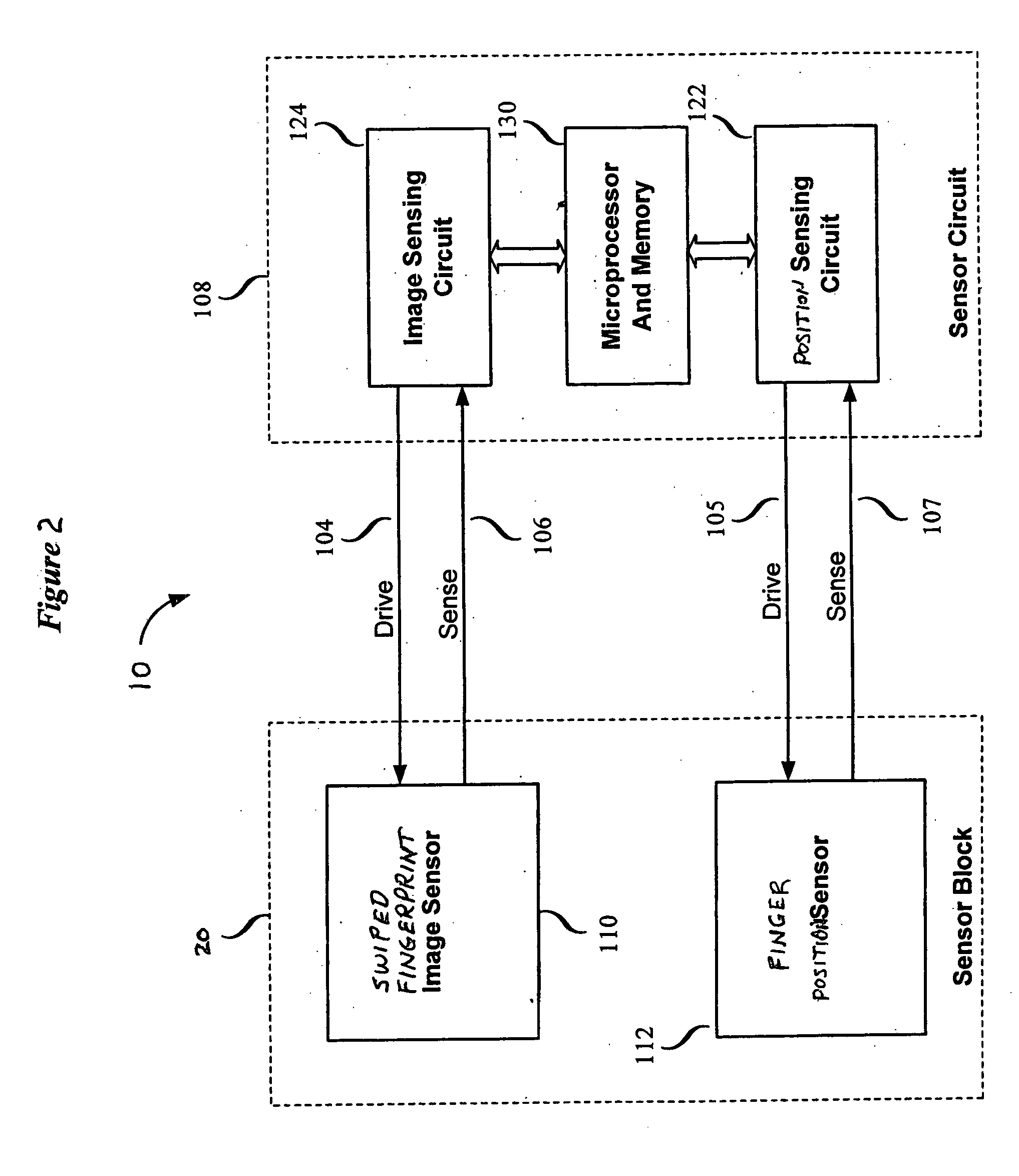
[0029] A fingerprint sensing system 10 in accordance with the present invention is shown in FIG. 1. A sensing portion of the system is shown in FIG. 2. As shown in FIG. 1, fingerprint sensing system 10 may include a sensor block 20, a processor 22, a visual display device 24 and an audio output device 26. The visual display device 24 may be a computer monitor, for example, in this embodiment. As shown in FIG. 2, sensor block 20 receives drive signals from and delivers sense signals to a sensor circuit 108. Sensor circuit 108 may be part of processor 22 shown in FIG. 1.

[0030] Sensor block 20 includes a swiped fingerprint image sensor 110 and a finger position sensor 112. Image sensor 110 and finger position sensor 112 may be fabricated on a single substrate as described below. Sensor circuit 108 includes an image sensing circuit 124, a position sensing circuit 122 and a microprocessor and memory 130. Image sensor 110 receives drive signals 104 from and delivers sense signals 106 to i...

second embodiment

[0073] A fingerprint sensing system 500 in accordance with the present invention is shown in FIG. 13. Like elements in FIGS. 1 and 13 have the same reference numerals. The fingerprint sensing system 500 differs from the fingerprint sensing system 10 in that the visual display device 24 is implemented as display lights, such as light-emitting diodes 510, 512, 514, 516 and 518. The light-emitting diodes 510-518 may be positioned in a row adjacent to sensor block 20 and may provide an indication of finger placement. It will be understood that a larger number of light-emitting diodes may be utilized within the scope of the present invention. The embodiment utilizing display lights provides a low cost alternative to the computer monitor in the embodiment of FIG. 1.

[0074] The light-emitting diodes are amber next to areas where finger contact is desired, and then are switched to green as finger contact is detected. When finger contact is complete and the finger is properly positioned to be...


PUM


Abstract

A method for assisting a user of a fingerprint sensing system includes sensing a position of a user's finger relative to a swiped fingerprint image sensor, and providing to the user, in response to the sensed finger position, an indication of finger placement relative to the fingerprint image sensor. The indication of finger placement may include a display on a computer monitor of actual finger placement and desired finger placement. The fingerprint sensing system may include an image sensor to sense a fingerprint on a swiped finger, a finger position sensor to sense the position of the finger relative to the image sensor, and processing apparatus to provide the indication of finger placement to the user.

Description

CROSS-REFERENCE TO RELATED APPLICATION [0001] This application claims the benefit of Provisional Application Ser. No. 60 / 564,791, filed Apr. 23, 2004, which is hereby incorporated by reference in its entirety.FIELD OF THE INVENTION [0002] This invention relates to systems and methods for electronically sensing biometric features of an object, such as a fingerprint. More particularly, the invention relates to methods and apparatus for assisting a user of a fingerprint sensing system wherein a fingerprint image is acquired by swiping a finger over an image sensor. BACKGROUND OF THE INVENTION [0003] Electronic fingerprint sensing has received increased attention as a technique for reliable identification of individuals. Electronic fingerprint sensing may be used in stationary equipment, such as security checkpoints, and in portable devices, such as mobile phones and other wireless devices, and smart cards. Accordingly, electronic fingerprint sensing systems are required to be compact, ...

Claims


Application Information

Patent Timeline
Patent Type & Authority Applications(United States)
IPC IPC(8): G06K9/00
CPCG06K9/00026G06V40/1335
Inventor GEOFFROY, DAVID J.BUXTON, JEFFREY J.
Owner SYNAPTICS INC
Why Eureka
Eureka Blog
Learn More