Axial-flow type fan having an air outlet blade structure

a technology of air outlet blades and axial flow, which is applied in the direction of machines/engines, mechanical equipment, liquid fuel engines, etc., can solve the problems of axial flow type fans in use, and achieve the effect of reducing air nois

Inactive Publication Date: 2005-11-10
SUNONWEALTH ELECTRIC MACHINE IND
View PDF14 Cites 15 Cited by
  • Summary
  • Abstract
  • Description
  • Claims
  • Application Information

AI Technical Summary

Benefits of technology

[0008] The primary objective of this invention is to provide an axial-flow type fan having an air outlet blade structure, which

Problems solved by technology

However, there exist several drawbac

Method used


Image

  • Axial-flow type fan having an air outlet blade structure
  • Axial-flow type fan having an air outlet blade structure
  • Axial-flow type fan having an air outlet blade structure

Examples


Embodiment Construction

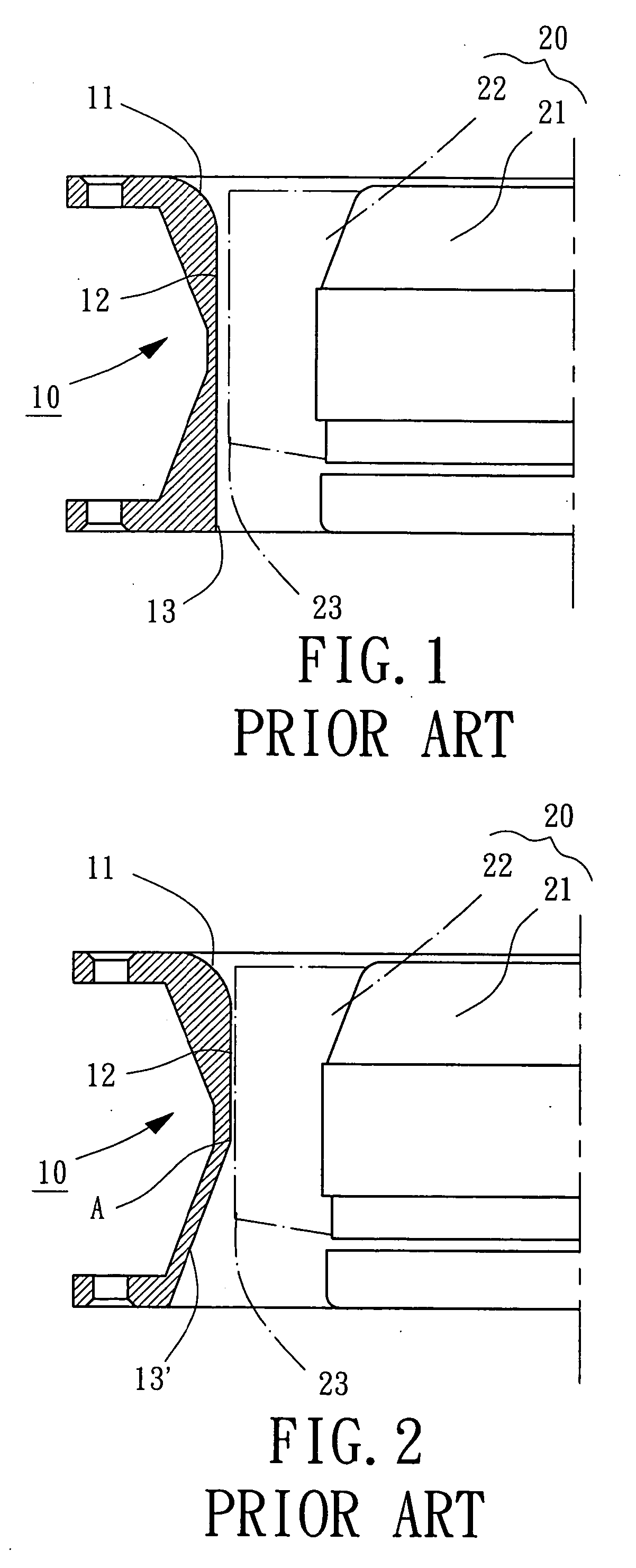
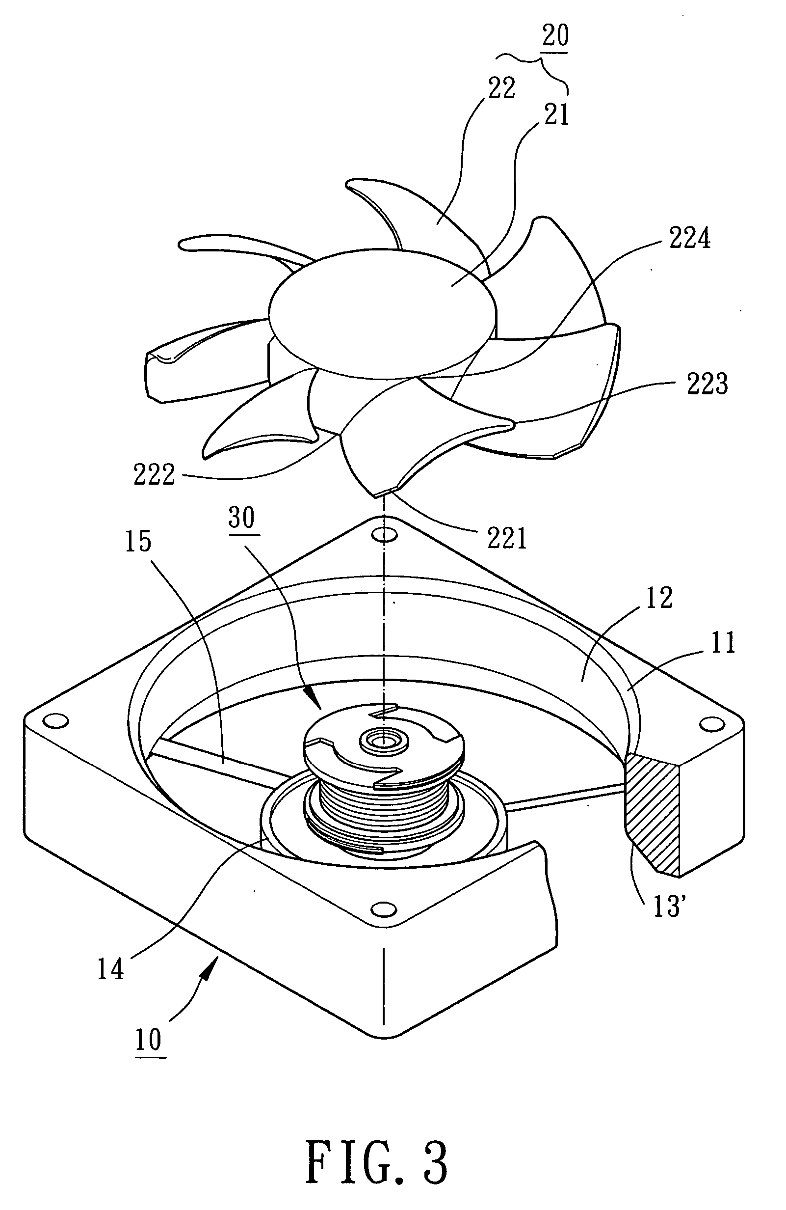
[0019] Referring to FIGS. 3 through 6, reference numerals of the first and second embodiments of the present invention have applied the identical numerals of the conventional fan structure, as shown in FIGS. 1 and 2. The construction of the fan structure in accordance with the embodiments of the present invention have similar configuration and same function as those of the conventional fan structure and detailed descriptions may be omitted.

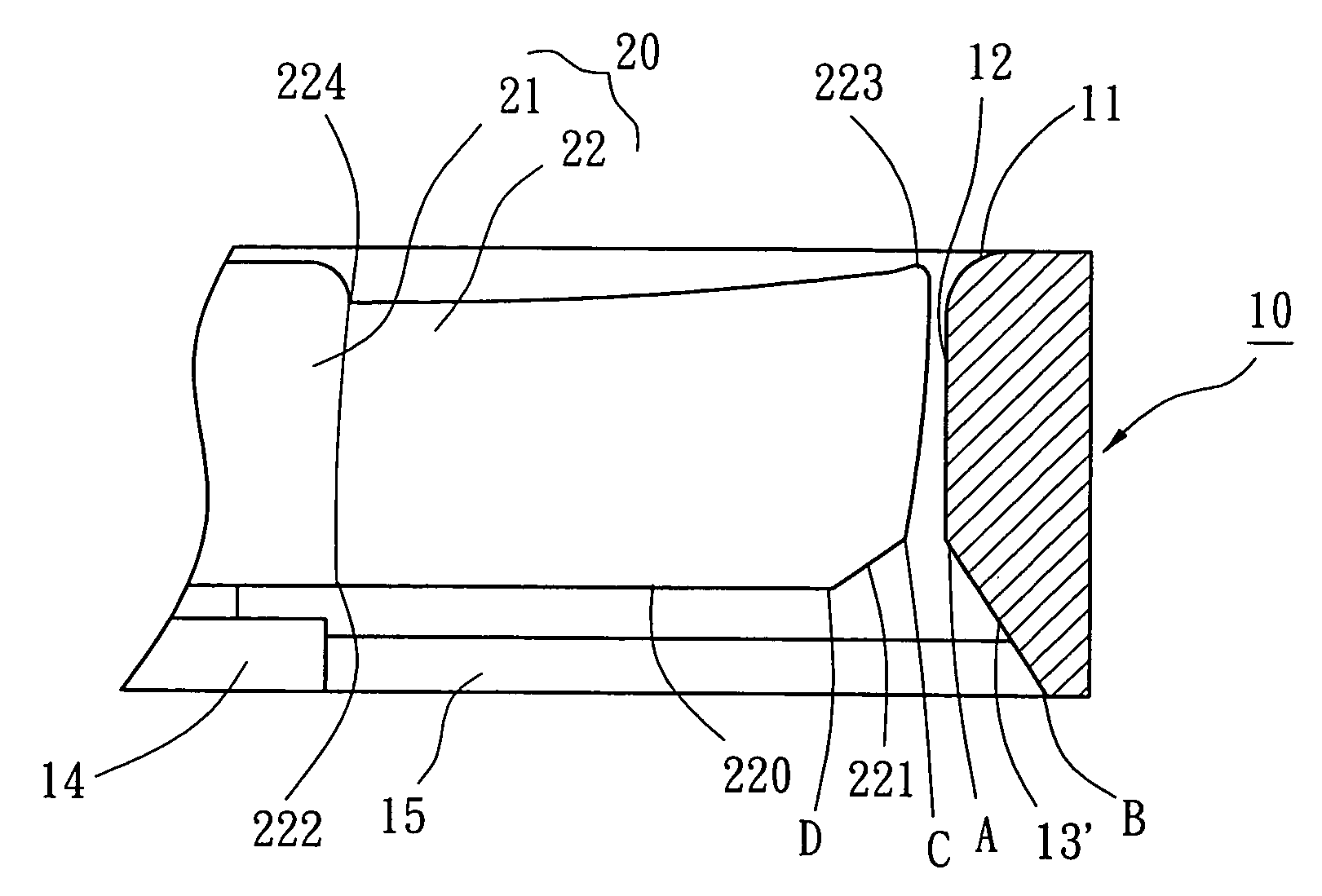
[0020] Referring to FIGS. 2 through 5, an axial-flow type fan in accordance with a first embodiment of the present invention includes a fan housing 10 and a fan wheel 20.

[0021] Referring again to FIGS. 3 through 5, construction of the fan housing 10 shall be described in detail. The fan housing 10 is made of plastic or metal material, and formed with a square or circular hollow body. The fan housing 10 consists of an air-boosting inlet 11, an air channel 12, an air-expanding outlet 13′, a base 14 and a plurality of supporting ribs 15. The air in...


PUM


Abstract

An axial-flow type fan includes a fan housing consisting of an air inlet, an air outlet and an air channel, and a fan wheel consisting of a hub and fan blades. The air channel of the fan housing accommodates the fan wheel which has end-cornered cutting blades proximate the air outlet of the fan housing. When the fan wheel is rotated, the end-cornered cutting blades are able to eliminate air turbulence and air noise in the air outlet of the fan housing.

Description

BACKGROUND OF THE INVENTION [0001] 1. Field of the Invention [0002] The present invention relates to an axial-flow type fan having an air outlet blade structure. More particularly, the present invention relates to an axial-flow type fan having an end-cornered cutting blade structure proximate an air outlet of a fan housing, thereby reducing air-shearing noise in operation. [0003] 2. Description of the Related Art [0004] Referring initially to FIG. 1, it illustrates a conventional fan housing structure having an air outlet connecting with an air inlet. The fan housing 10 forms an air-boosting inlet 11, an air channel 12 and an air outlet 13. A fan wheel (impeller) 20 is accommodated in the air channel 12, and consists of a hub 21 and a plurality of fan blades 22 arranged about a rotary axis of the hub 21. Each of the fan blades 22 has an air outlet corner 23. In operation, when the fan wheel 20 is rotated, the fan blades 22 drives air and the air outlet corner 23 may cause air turbul...

Claims


Application Information

Patent Timeline
IPC IPC(8): F01D5/10F04D29/54
CPCF04D29/545
Inventor HORNG, ALEXHONG, YIN-RONG
Owner SUNONWEALTH ELECTRIC MACHINE IND
Why Eureka
Try Eureka