Dynamic pilot power in a wireless communications system

a wireless communication system and dynamic pilot technology, applied in the field of communication systems, can solve the problems of complicated balancing act between coverage and interference, inability of mobile stations near the fringe of the cell to establish or maintain and inability to achieve the effect of establishing or maintaining communication with the base station

Inactive Publication Date: 2005-11-10
LUCENT TECH INC
View PDF3 Cites 90 Cited by
  • Summary
  • Abstract
  • Description
  • Claims
  • Application Information

AI Technical Summary

Problems solved by technology

Pilot power settings, however, are a complicated balancing act between coverage and interference.
For example, if pilot power is set too low, then coverage at the fringes of a cell may be compromised as the load on the cell is increased by more mobile stations entering the cell.
Thus, as the load in the cell increases, it is more likely that a mobile station near the fringe

Method used


Image

  • Dynamic pilot power in a wireless communications system
  • Dynamic pilot power in a wireless communications system
  • Dynamic pilot power in a wireless communications system

Examples


Embodiment Construction

[0016] Illustrative embodiments of the invention are described below. In the interest of clarity, not all features of an actual implementation are described in this specification. It will of course be appreciated that in the development of any such actual embodiment, numerous implementation-specific decisions must be made to achieve the developers' specific goals, such as compliance with system-related and business-related constraints, which will vary from one implementation to another. Moreover, it will be appreciated that such a development effort might be complex and time-consuming, but would nevertheless be a routine undertaking for those of ordinary skill in the art having the benefit of this disclosure.

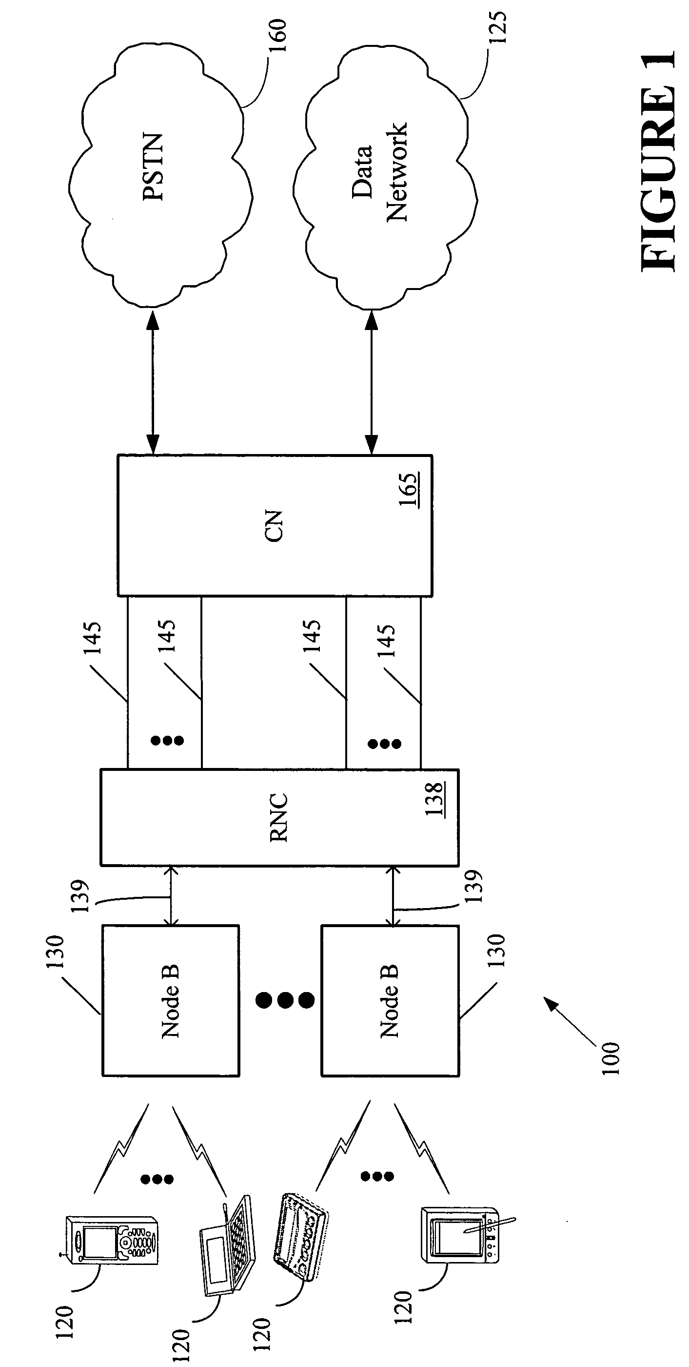
[0017] Turning now to the drawings, and specifically referring to FIG. 1, a communications system 100 is illustrated, in accordance with one embodiment of the present invention. For illustrative purposes, the communications system 100 of FIG. 1 is a Universal Mobile Telephone S...


PUM


Abstract

A method is provided for controlling pilot power in a communications system. The method comprises determining a load associated with a cell in the communications system, and setting pilot power at a level associated with the determined load. In one exemplary embodiment, pilot power is set at a first low level in response to the determined load being less than a preselected setpoint and at a second, higher level in response to the determined load being greater than the preselected setpoint.

Description

BACKGROUND OF THE INVENTION [0001] 1. Field of the Invention [0002] This invention relates generally to a communications system, and, more particularly, to controlling the flow of data between a user and a communications base station. [0003] 2. Description of the Related Art [0004] In the field of wireless telecommunications, such as cellular telephony, a system typically includes a plurality of base stations distributed within an area to be serviced by the system. Various users within the area, fixed or mobile, may then access the system and, thus, other interconnected telecommunications systems, via one or more of the base stations. Typically, a mobile user maintains communications with the system as he / she passes through an area by communicating with one and then another base station, as he / she moves. Each area covered by a base station is commonly referred to as a cell. [0005] The base stations are typically located in a grid pattern with overlapping areas of coverage to ensure ...

Claims


Application Information

Patent Timeline
IPC IPC(8): H04W16/06
CPCH04W16/06
Inventor JUGL, ENRICOSCHACHT, MIRKODERAKHSHAN, FARIBORZ
Owner LUCENT TECH INC
Why Eureka
Try Eureka