
Guide adapter with claw contour

a technology of adapter and contour, which is applied in the direction of power-driven reciprocating saws, metal sawing accessories, manufacturing tools, etc., can solve the problems of torque generation and unsuitability of prior art guide adapters

Inactive Publication Date: 2005-11-17
HILTI AG
View PDF12 Cites 18 Cited by
  • Summary
  • Abstract
  • Description
  • Claims
  • Application Information

AI Technical Summary

Benefits of technology

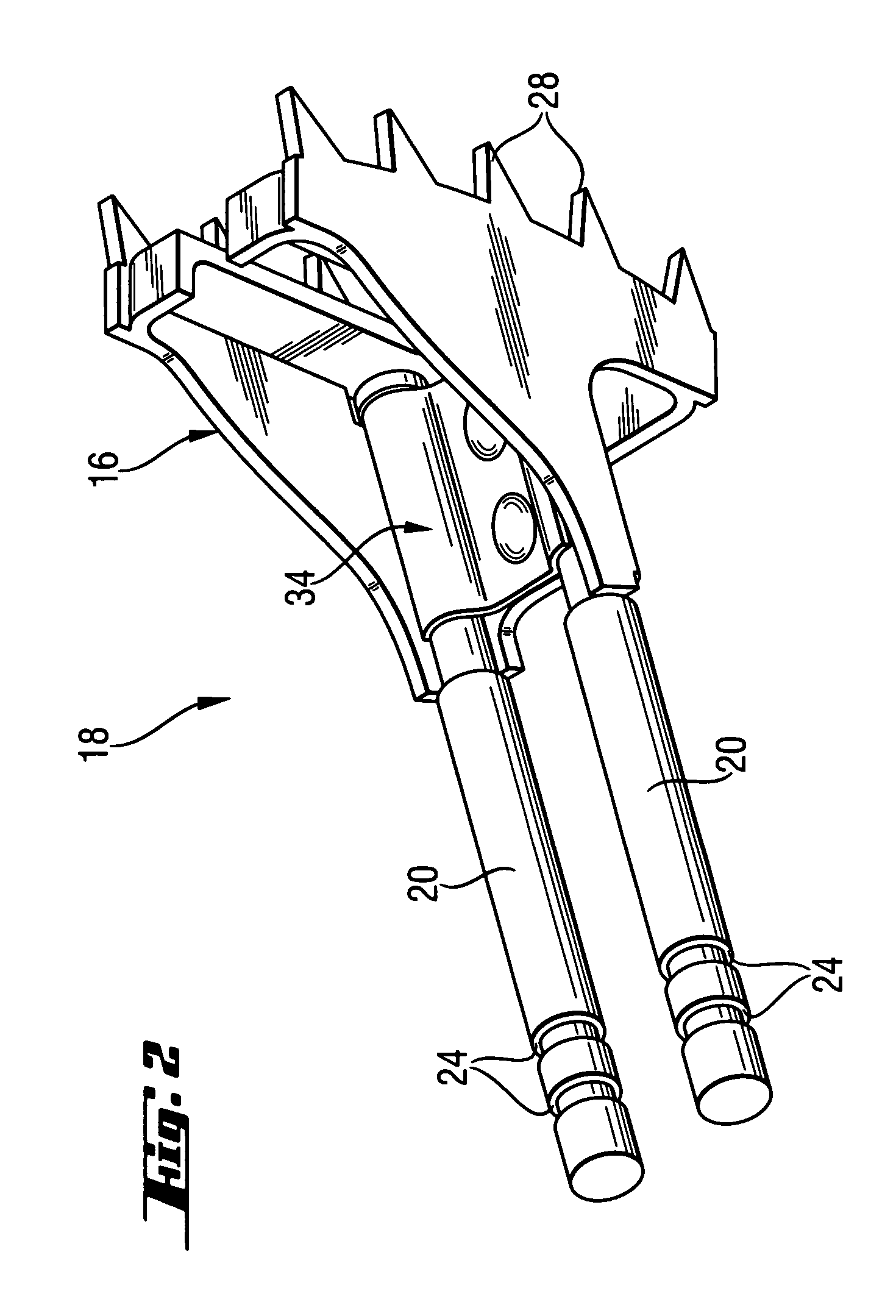
[0007] Advantageously, the teeth are arranged in two parallel rows, wherein the hold of the toothed contour on the surface of the work piece and the guiding of the saw blade are improved.
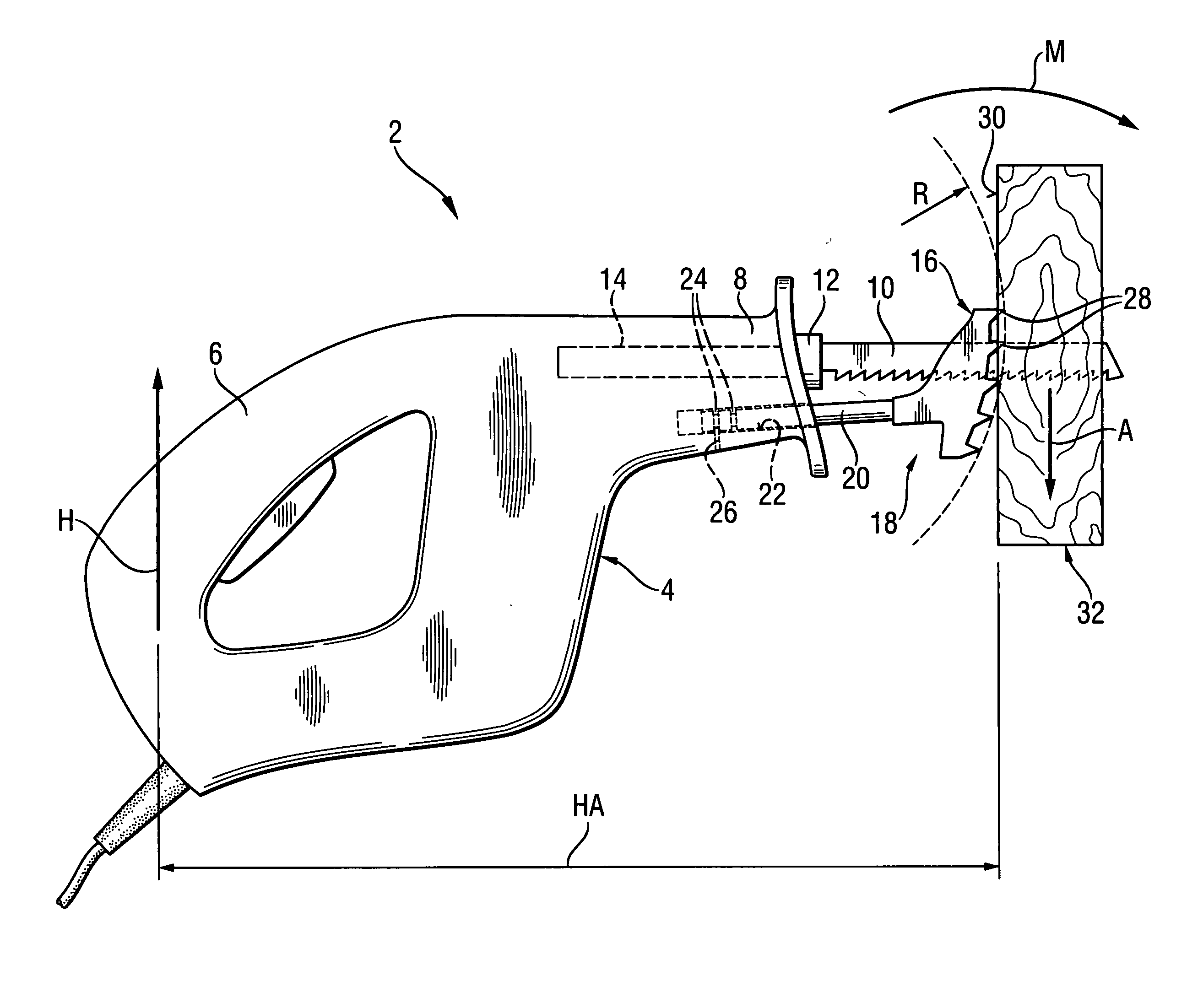
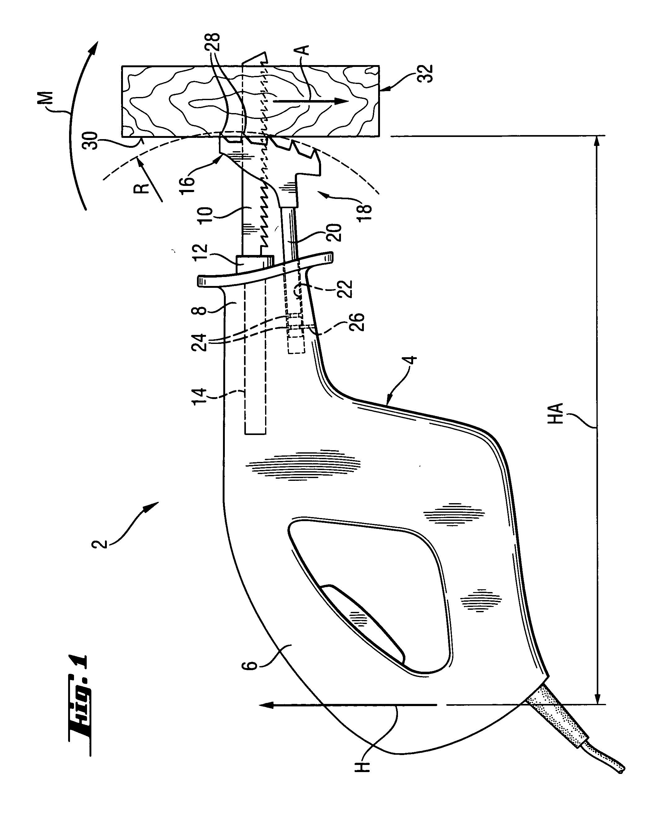
[0008] Preferably, the contacting element is fastened rigidly to the carrier means. In this manner, a maximum length of the useful mechanical advantage is obtained, which reaches from the posterior end of the saber saw over its housing, the carrier means and the contacting element onto the claw contour. In this manner, the pivot point, about which this maximum mechanical advantage acts, is defined by the tips of the teeth that grip into the surface of the concerned work piece. A high contact pressure of the saw blade against the work piece can be obtained comfortably.
[0010] When this is done, the teeth are preferably arranged along a circular path, whose radius is in a range from 10 to 30 cm, in particular 20 cm, whereby the torque about the tooth control can be generated comfortably.
[0013] It is particularly advantageous, if the rods have at least two engagement recesses in the axial direction. In this manner, the spacing of the contacting element to the saber saw and the length of the useful mechanical advantage can be adapted to a planned cutting operation.

Problems solved by technology

For other demolition work such as reducing wooden walls, the prior art guide adapter is unsuitable because of the limited displacement path of the hook element.
A relatively high pressure of the saw blade against the work piece results from the torque generated in this process.

Method used


Image

  • Guide adapter with claw contour
  • Guide adapter with claw contour
  • Guide adapter with claw contour

Examples


Embodiment Construction

[0018]FIG. 1 shows a saber saw 2 with a housing 4. A main handle grip 6 is formed at a posterior end of housing 4. At a tool-end facing away form the posterior end, the housing 4 forms a device neck 8, which serves as an additional hand grip.

[0019] At a free end of the device neck 8, a saw blade 10 projects from the housing 4, which is fastened using a tool receptacle 12 on a tool spindle 14 of the saber saw 2. The saw blade 10 passes through a contacting element 16 of a guide adapter 18, which is represented in FIG. 2 separated from the saber saw.

[0020] The guide adapter 18 can be secured at the device neck 8 of the saber saw 2 using carrier means such as two rods 20 arranged parallel to each other and having a round cross-section. For securing, the rods 20 are inserted into hollow cylindrical receptacles 22 on the device neck 8. The hollow cylindrical receptacles 22 thus form a free cross-section, which corresponds to the cross-section of the rods 20.

[0021] For axial securing i...


PUM

PropertyMeasurementUnit
Radiusaaaaaaaaaa
Radiusaaaaaaaaaa

Abstract

A guide adapter (18) has carrier means removably secured on a tool-side end of a housing (4) of a saber saw (2) and a contacting element (16) for contacting on a work piece (32) to be worked. The contacting element (16) has a claw contour for securing on a surface (30) of the work piece (32). The carrier means has a clamping contour for immobile clamping on the housing (4) and the claw contour is transiently affixed relative to the carrier means. The claw contour has a plurality of teeth (28), which are directed away from the carrier means.

Description

BACKGROUND OF THE INVENTION [0001] The invention relates to a guide adapter with carrier means for removable attachment to a tool-side end of a housing of a saber saw. Moreover, the guide adapter has a contact element for contacting a work piece to be worked on, wherein the contact element is provided with a claw contour for attaching to a surface of the work piece. Further, the invention relates to a saber saw with this type of guide adapter. [0002] This guide adapter having a claw contour is used primarily for immobilizing a saber saw on a work piece to be worked on comprised of softer material into which the claw contour can partially penetrate to prevent slipping. Such work pieces can be broken parts made of wood or tree branches. [0003] U.S. Pat. No. 6,484,409 discloses a saber saw, whose neck holds a guide adapter. A displaceable hook element is arranged on a guide element on the guide adapter, wherein a claw contour is formed on said hook element. In this case, the teeth of t...

Claims


Application Information

Patent Timeline
IPC IPC(8): B27B21/08B27B19/09
CPCB27B19/09B23D51/02
Inventor NEUMEIER, MICHAEL
Owner HILTI AG
Learn More