

Fluidized bed reactor
a technology of fluidized bed and reactor, which is applied in the field of fluidized bed device, can solve the problems of small amount accepted material loss and particle loss by fluidization flow, and achieve the effect of simple cleaning ability
- Summary
- Abstract
- Description
- Claims
- Application Information
AI Technical Summary
Benefits of technology
Problems solved by technology
Method used
Image

Examples
Embodiment Construction
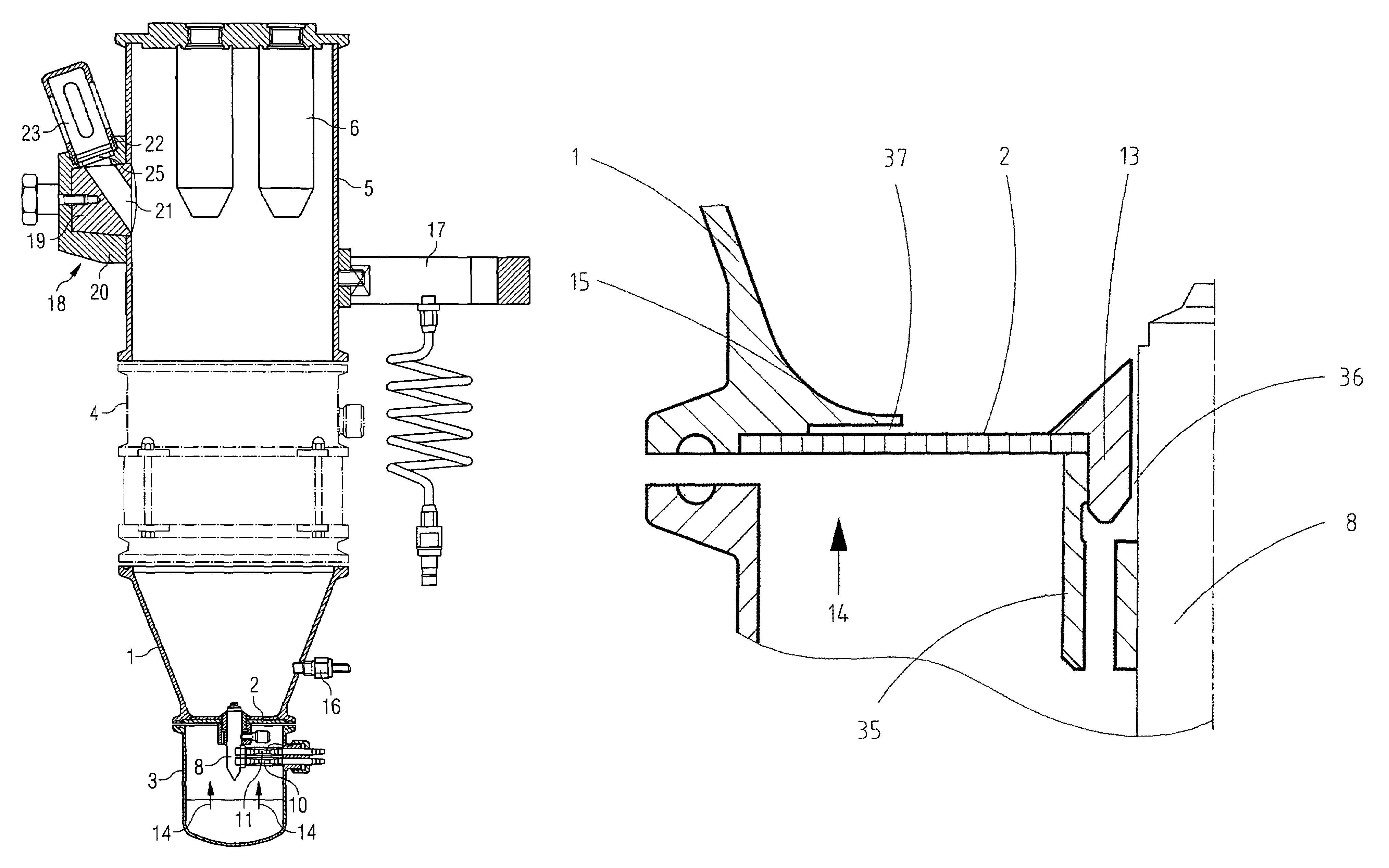
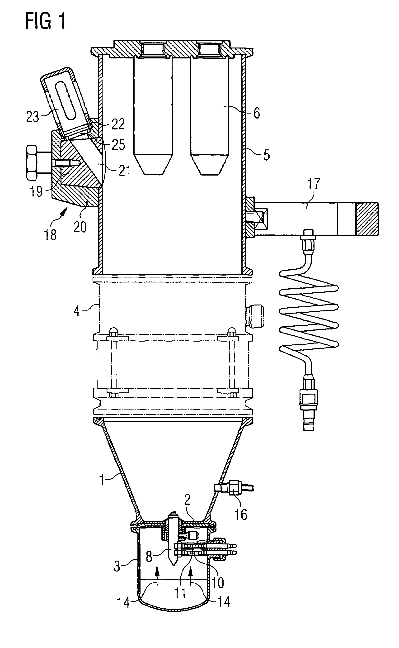
[0020]The device represented in FIG. 1 as its main constituents comprises a generally funnel-like product container 1 that via a sieve bottom 2 is connected to a lower part 3. An optional transition housing 4 may be arranged above the funnel-like product container. This is indicated by the dot-dash representation. Furthermore, a filter housing 5 may be arranged above the transition housing 4, into which filters 6, for example, metal filters, are inserted. However other types of filters may also be used. The product container 1, the lower part 3, the transition housing 4 and filter housing 5 may be releasably connected to one another, e.g., using releasable quick-connections such a clamp / clip connections which for example are designed from clamping rings engaging over the outer edges of the various housing parts. Certain embodiments may have sealing rings (not shown) inserted between the parts.
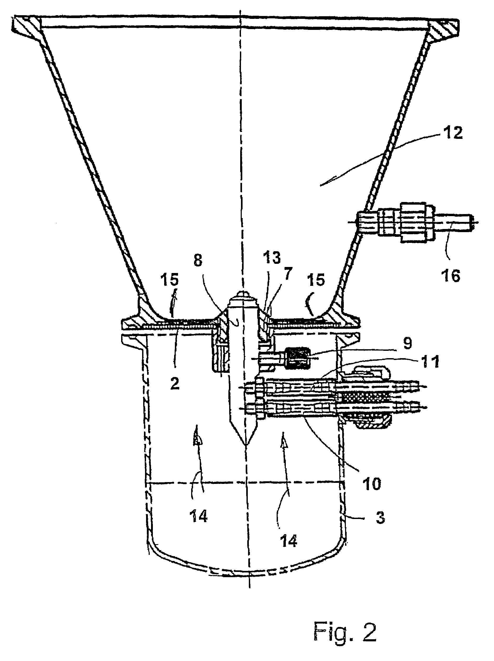
[0021]As may be recognized in more detail in FIG. 2, a nozzle holder 7 is applied centrally...
PUM
| Property | Measurement | Unit |
|---|---|---|
| height | aaaaa | aaaaa |
| width | aaaaa | aaaaa |
| width | aaaaa | aaaaa |
Abstract
Description
Claims
Application Information