Plain bearing shell with slide face surface geometry which is profiled in the axial direction

a surface geometry and bearing technology, applied in the direction of bearings, sliding contact bearings, shafts, etc., can solve the problems of affecting the operating affecting the operation performance of the engine, and a large amount of oil loss at the plain bearing position, so as to reduce the probability of oil film tear, reduce effort, and maintain the guiding accuracy of the shaft in the bearing.

Active Publication Date: 2015-07-14
FEDERAL MOGUL WIESBADEN
View PDF16 Cites 7 Cited by
  • Summary
  • Abstract
  • Description
  • Claims
  • Application Information

AI Technical Summary

Benefits of technology

[0014]One object of the invention is to provide a bearing shell with which there is a reduced probability of an oil film tear in the edge region of the bearing shell (viewed in the axial direction) owing to the bending or tilting of a shaft positioned therein, while at the same time the guiding accuracy of the shaft in the bearing is maintained. A further object of the invention is to provide a method for producing such a bearing, with which the profiling of the slide face can additionally be realized with reduced effort.
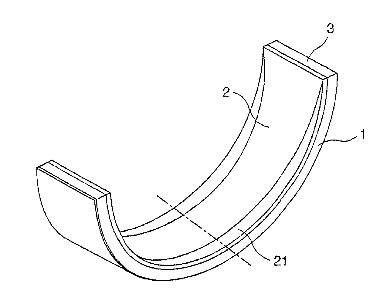
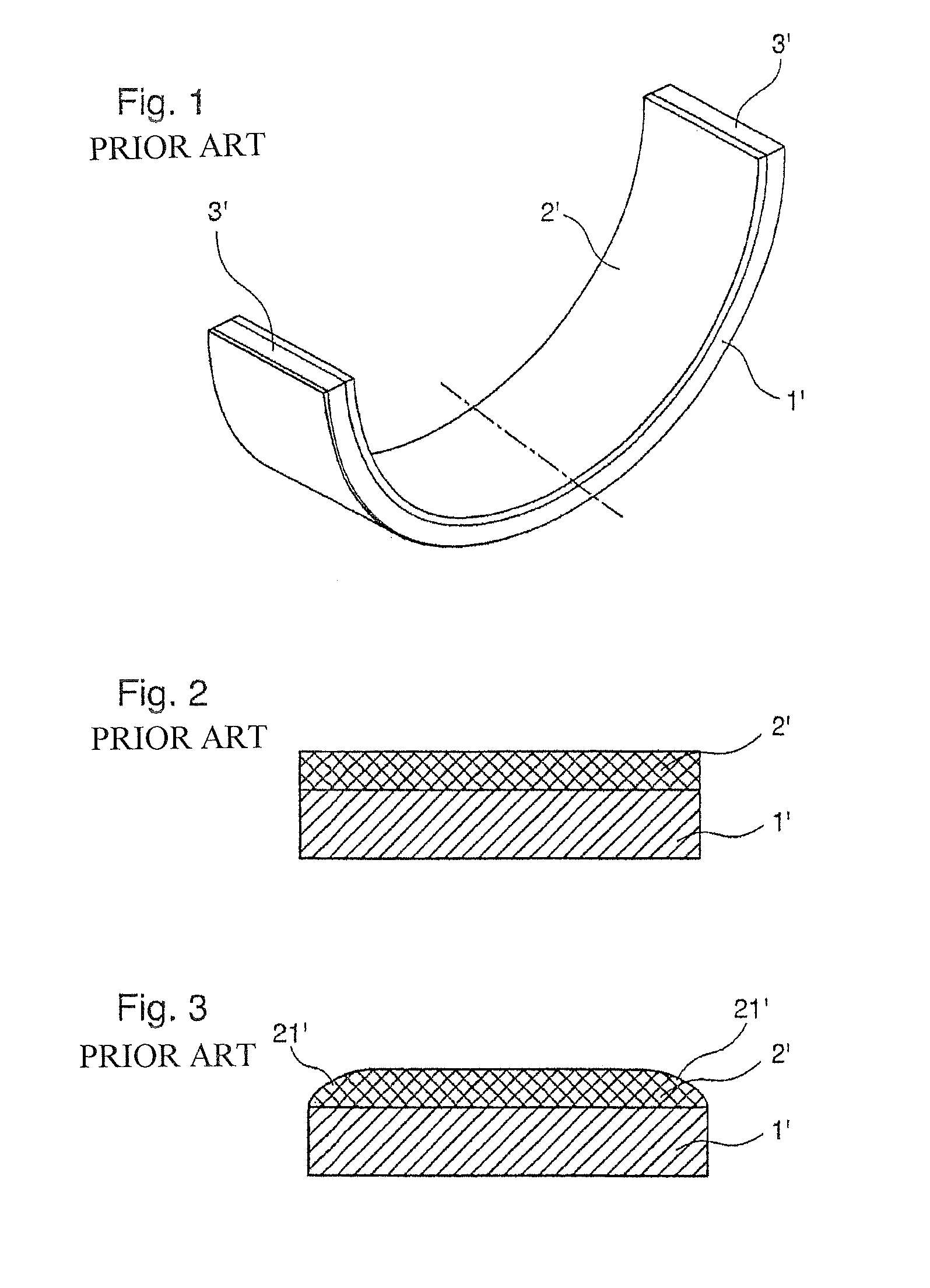
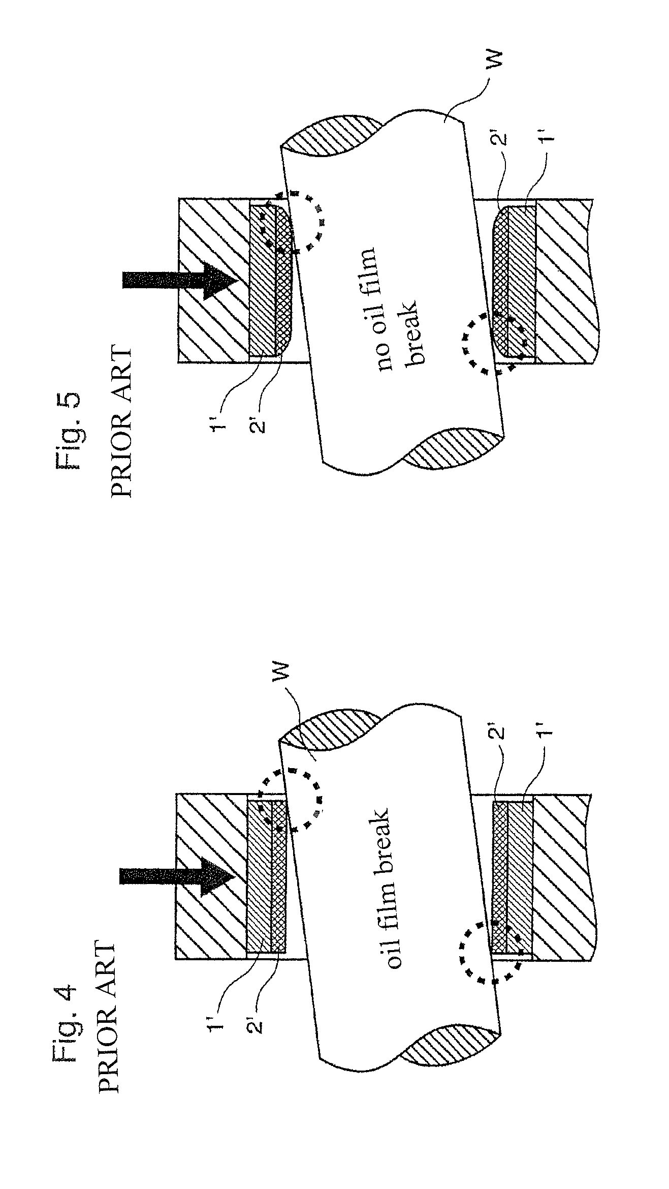
[0015]The plain bearing shell according to the invention comprises a slide face which is convexly curved in the axial direction in the region of the apex (viewed in the circumferential direction of the bearing shell) and at least at the edge regions. The curvature is most pronounced at the apex and decreases continuously in the circumferential direction of the plain bearing shell toward the two partial surfaces. Owing to the bending or tilting of the shaft that occurs during operation, it is sufficient to implement the sloping geometry most markedly at the apex of the plain bearing shell. Thus, regions of the slide face remain, away from the apex region, in which the slide face is only slightly curved or is not curved at all. The guiding of the shaft is therefore improved as compared with a slide face continuously curved in the circumferential direction. The convex curvature reduces the likelihood of a tear in the oil film in the edge regions of the bearing. As a result of the curvature, in contrast to an incline of the end regions directed at the deformation of the bearing, different tilting angles and / or degrees of bending of the shaft are taken into consideration. In this way, increased play between the shaft and the slide face owing to wear, which has a direct influence on the tilting angle and bending amplitude that occurs, is taken into account.
[0016]Preferably, the curvature continuously tapers off to zero in the circumferential direction such that no convex profiling is provided on the two partial surfaces. This further improves the guiding accuracy of the bearing. Moreover, exposed regions, which indicate a reduction in the wall thickness of the bearing shell in the regions of the partial surfaces, can be particularly easily integrated in this way. The exposed regions prevent inaccuracies at the joins of the two bearing shells leading to the inner edge of a partial surface at a join protruding inwardly, particularly in view of the fact that the bearing shells are pressed together with high pressure in order to form a bearing. As a result of this, the operating characteristics of the shaft are improved and a reduction in the wear of the bearing of the shaft is achieved. For the production of the exposed regions, the drill spindle comprises a second cutting cartridge in addition to the first cutting cartridge for cutting the bearing shell to a certain wall thickness (continuously or non-continuously). The first cutting cartridge is preferably arranged so as to be offset behind the second cutting cartridge in the feed direction of the tool. Preferably, the two cutting cartridges are mounted on the drill spindle such that they are opposite one another at 180°. Exposed regions can be formed at the ends of the bearing shell by positioning the second cutting cartridge in a suitable manner and inclining the drilling tool with respect to the bearing shell axis during machining.
[0017]Preferably, the slide face of the bearing shell is curved in the axial direction at the edge regions and is flat therebetween, the transition between the curved region and the flat region being continuous. In this way, the guiding accuracy of the bearing shell is increased. Avoiding a non-continuous transition between the flat region and the curved region reduces the probability of a tear in the oil film in the transition region since a non-continuous transition in the case of a tilting or bending of the shaft has a similar effect to the edge of a linear, non-round slide face.
[0018]Preferably, the curvature radius in the edge regions, viewed in the axial direction, is constant. In other words, in addition to the flat region, for which no curvature radius is defined, the bearing shell comprises in the axial direction a curvature having a constant curvature radius in the edge regions. In this way, the construction of the bearing shell and the production of the same are simplified. A constant curvature radius causes, in contrast to a slant, an increasing reduction in the thickness of the bearing shell toward the edge. Various tilting angles and / or degrees of bending of the shaft are compensated for in this way.
[0021]Preferably, the curvature radius in the axial direction over the entire width is constant in order to ensure, with a simple method of production, good adjustability to various pitches of the shaft relative to the axial direction of the bearing shell.

Problems solved by technology

High oil pressures between the outer regions of the plain bearing shell, in the axial direction of the plain bearing shell, and the shaft lead to a great deal of oil loss at the plain bearing position during operation.
The tearing of the oil film between the plain bearing shell and the shaft results in an extremely high level of wear and material fatigue in the region of the contact zone between the plain bearing shell and the shaft.
One cause for the wear of the slide face at the bearing and the shaft contained therein is a minimal bending or tilting of the shaft under a load, as shown schematically in FIG. 4 with a greatly exaggerated tilting of the shaft W. If the bearing is a connecting rod bearing or a main bearing in a combustion engine that is subject to high loads, these uneven loads of the shaft on the bearing ultimately have an adverse effect on the operating performance of the engine.
In particular, serious deficiencies having a considerable effect on the operating state of an engine may occur particularly in the regions of the plain bearing shell that are subject to the highest loads, the apex of the plain bearing shell.
The deficiencies caused by this may lead to disruptions to the operating state of the engine or even to a complete breakdown of the engine.
The location-dependent oil pressure causes the slide face of the bearing to be concavely deformed such that even if the slide face is configured to be round at the edge regions, the oil film may tear.
However, a greater degree of roundness is not consistent with maximizing the load-bearing region.
A slight rounding off of the ends of the bearing shell does not sufficiently solve the problem of the oil film tearing owing to the bending or tilting of the shaft.
However, a very round configuration of the slide face reduces the guiding accuracy of the shaft in the bearing.

Method used


Image

  • Plain bearing shell with slide face surface geometry which is profiled in the axial direction
  • Plain bearing shell with slide face surface geometry which is profiled in the axial direction
  • Plain bearing shell with slide face surface geometry which is profiled in the axial direction

Examples


Embodiment Construction

[0039]FIG. 6 shows a bearing shell 1 having a slide face profile 21 rounded off convexly at the edge regions (viewed in the axial direction of the bearing shell 1), the convex curvature tapering off toward the partial surfaces 3.

[0040]As a result of the curvature 21 at the edge regions, the impacts of a bending or tilting of a shaft in the bearing shell 1 operating under a load are mitigated with respect to wear and operating characteristics since the probability of an oil film tear at the edge of the bearing shell 1 is reduced. It should be noted that the curvature in FIGS. 3, 5, 6 and 7A to 7D is greatly exaggerated for illustrative purposes.

(Section A-A)

[0041]According to FIG. 7A, the profile of the slide face 2 at the apex of the plain bearing shell 1 is convexly curved in the axial direction over the entire length thereof with a constant curvature radius. This profile continuously decreases and tapers off toward the two partial surfaces 3 in the circumferential direction of the...


PUM

PropertyMeasurementUnit
thicknessaaaaaaaaaa
thicknessaaaaaaaaaa
thicknessaaaaaaaaaa

Abstract

A plain bearing shell includes a slide face of which, in the region of the apex of the plain bearing shell, is convexly curved in the axial direction at least at the edge regions, wherein the curvature is at its most pronounced at the apex of the plain bearing shell and decreases continuously in the circumferential direction of the plain bearing shell toward the two partial surfaces. A method for producing such a plain bearing shell is also provided.

Description

BACKGROUND OF THE INVENTION[0001]1. Technical Field[0002]The invention relates to a plain bearing shell having a slide face which is partially convexly curved. The invention also relates to a method for producing a plain bearing shell of this type.[0003]2. Related Art[0004]The machining of the slide faces of bearing shells is carried out by drilling out the bearing shells. This involves a drill spindle rotating at a rotation speed X (rev / min) and moving at a feed rate Y (mm / rev) in the axial direction of the bearing shell to be machined. The drilling out is carried out, for example, using a drill spindle with two cutting cartridges positioned opposite one another at 180° being installed in the spindle head thereof.[0005]The drill spindle comprises a first cutting cartridge for cutting a bearing shell to a certain wall thickness (continuously or non-continuously) and, optionally, a second cutting cartridge for forming so-called exposed regions. An exposed region is to be understood a...

Claims


Application Information

Patent Timeline
Patent Type & Authority Patents(United States)
IPC IPC(8): F16C9/02F16C25/04F16C33/04F16C17/02F16C23/04F16C33/14F16C9/04
CPCF16C33/04F16C9/04F16C17/022F16C23/041F16C33/046F16C33/14F16C2360/22Y10T408/03F16C2220/60F16C2240/50F16C23/04F16C17/02
Inventor ROSSMANITH, RALFRITTMANN, STEFAN
Owner FEDERAL MOGUL WIESBADEN
Why Eureka
Try Eureka