Method and apparatus for creating circumferential flat surfaces on round cross section polymer optical fiber

a technology of polymer optical fiber and circumferential flat surface, which is applied in the field of apparatus and method of creating circumferential flat surface on the circumference of such fiber, can solve problems such as inconvenient operation, and achieve the effect of increasing the angular deviation

Inactive Publication Date: 2007-04-17
DIEMOUNT
View PDF9 Cites 7 Cited by
  • Summary
  • Abstract
  • Description
  • Claims
  • Application Information

AI Technical Summary

Benefits of technology

[0014]In one embodiment, it is advantageous for the polished surfaces of the POFs to be joined to be coated in vacuum with an approximately 100 nm thick layer sequence of SiO2, Ag, and SiO2 before joining same. As a result, the cross-talk attenuation is increased quite considerably, namely up to 60 dB, without an excess loss being essentially aggravated thereby. Such a coating is preferably carried out at temperatures below 70° C. so that the POF is not damaged or even destroyed.
[0016]Tests with a coating of 100 nm HMDS, 100 nm Al, and 100 nm HMDS have shown that the couplers manufactured from POFs processed in this manner reveal almost the same quality as couplers whose POFs were provided with the above-mentioned layer sequence of SiO2, Ag, and SiO2. Compared to the latter the first mentioned ones have the advantage to be easier and more cost-effective in manufacture. HMDS is the abbreviation for hexamethyldisilane, which is predominantly used in semiconductor technology as an adhesive before applying a photo-resist onto a substrate. HMDS layers in connection with an Ag layer are also advantageous. The layer thicknesses are not restricted to the above-mentioned examples. HMDS furthermore has the property favorable for the invention that its refractive index is lower than that of the core material of the POF, which preferably consists of PMMA. This supports a total reflection on the interface between the POF and the HMDS layer. Furthermore, the HMDS tightly seals the embedded aluminum and thereby prevents corrosion of the aluminum. If silver is used instead of aluminum between the HMDS layers, the corrosion-protecting effect of the HMDS cover layer is even more meaningful.
[0026]2. the method can be adapted by enlarging the diameter and the length of the mandrel such that a very large number of splitters may be manufactured by one single longitudinal turning process. For example, by use of a mandrel of a diameter of 100 mm and a length of 300 mm, the components of 100 splitters can be manufactured in one processing step. If a large mandrel having a diameter of 400 mm and a length to 2 m is used, the manufacture of the components of 4000 splitters in one single longitudinal turning process becomes possible. The size of the mandrel and thus the output of the parts per processing step are determined only by the size of the available lathe.
[0027]It is advantageous if the mandrel has a helically-extending circumferential groove into which the POF may be inserted. The guide of the POF on the mandrel is thereby improved. It is also advantageous if the POF is wound onto the mandrel at a small strain. This also improves the position stability. Moreover, the inner stress of the POF frozen in the longitudinal direction of the POF is compensated by the strain.
[0032]It is also possible to design the plane faces, of the POF pieces created by turning-off, in a manner that they extend from the circumference inclined towards one of the free ends of the POF pieces. In this case, the mandrel must be dimensioned such that, starting out from a largest radius, the radius of the mandrel linearly decreases on both sides with an increasing angular deviation from the point of largest radius. Two POF pieces composed to form a pair then together form a circular face and cross section only on their end faces, which makes the support in a splitter housing more complicated compared to the above-mentioned solution using a cylindrical sleeve as a housing.

Problems solved by technology

Higher cutting speeds are possible, but a limiting factor is a possible unbalance of the mandrel with the polymer optical fiber wound thereon, so that in case of higher speeds vibrations may be generated, which provide imprecise working results.

Method used


Image

  • Method and apparatus for creating circumferential flat surfaces on round cross section polymer optical fiber
  • Method and apparatus for creating circumferential flat surfaces on round cross section polymer optical fiber
  • Method and apparatus for creating circumferential flat surfaces on round cross section polymer optical fiber

Examples


Embodiment Construction

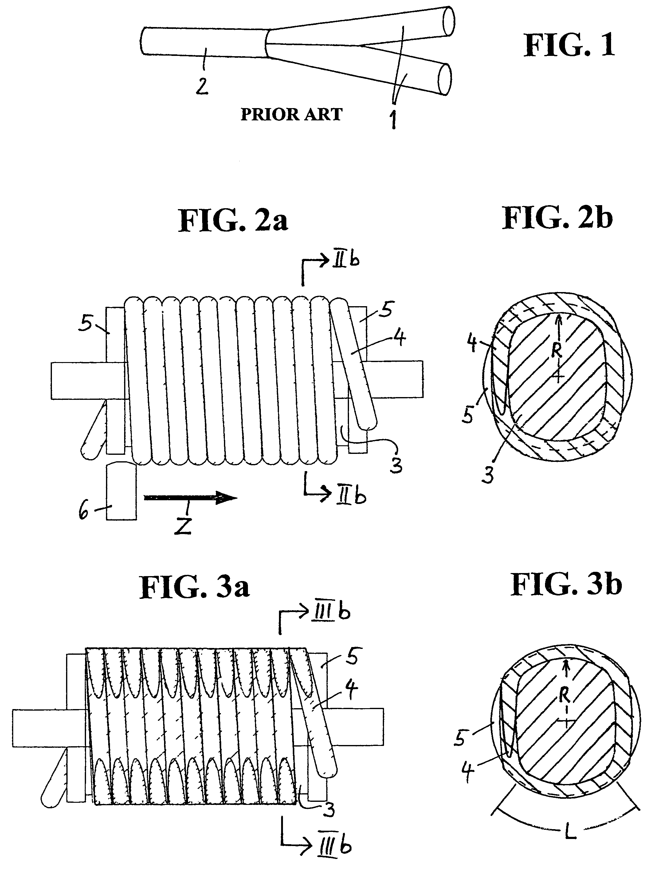
[0041]FIG. 1 shows the basic structure of a known polished coupler composed of three POFs, which are joined on their polished ends. This view can be derived from the above-mentioned publication of Daum et al. The polished coupler includes two POF pieces 1, whose circumferential surfaces are obliquely ground with high surface quality, i.e., polished in the area of a respective one of their ends, such ends abutting one another at their planar polished faces so that their axes extend at an acute angle with respect to one another. Furthermore, the polished coupler according to FIG. 1 comprises a third POF piece 2. The end faces of the obliquely polished POF pieces 1 together form a circular surface having a diameter that corresponds to the diameter of the third POF 2. All end faces are planar and polished to minimize stray loss.

[0042]A method according to the invention will now be explained with reference to the drawing figures.

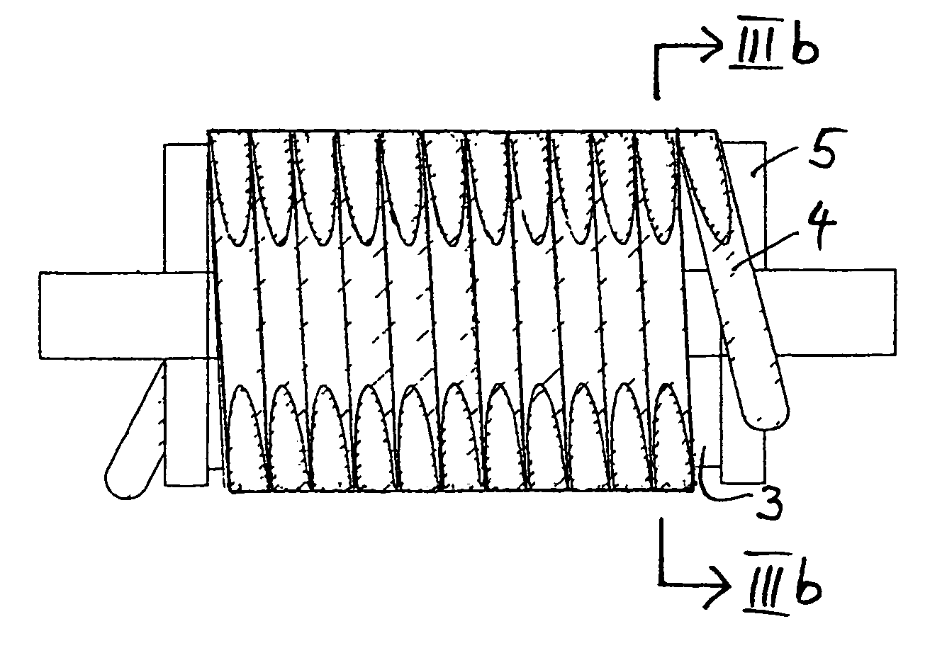
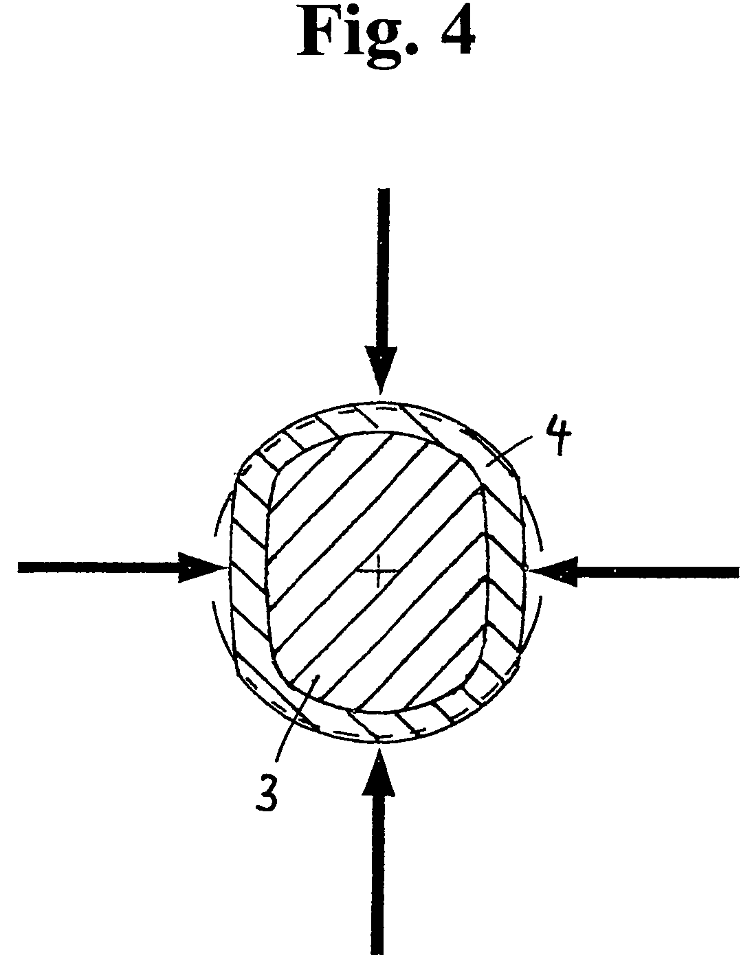
[0043]According to FIG. 2a, a POF 4 is wound onto a mandrel...


PUM

PropertyMeasurementUnit
thicknessaaaaaaaaaa
thicknessaaaaaaaaaa
thickaaaaaaaaaa

Abstract

For creating flat surfaces along the circumference of a polymer optical fiber of a round cross section by machining, the polymer optical fiber is wound onto a mandrel in a plurality of windings, the mandrel having a generally non-circular cross section with at least one projecting sector in which the radius is constant or, starting from an apex of the largest radius, in which the radius linearly decreases on both sides with an increasing angular distance to the apex, the machining including using a cutting chisel of a high quality for turning-off the polymer optical fiber in the projecting sector of the mandrel. Subsequently, the polymer optical fiber is cut to several pieces that can be used for the manufacture of optical splitters.

Description

CROSS REFERENCE TO RELATED APPLICATION[0001]This application is a continuation of PCT application PCT / EP2004 / 012928 , filed Nov. 15, 2004 by inventor Hans Kragl, and claims priority to German application DE 103 54 008.3 , filed Nov. 19, 2003.FIELD OF THE INVENTION[0002]The present invention generally refers to the manufacture of optical couplers for polymer optical fiber (hereinafter referred to as “POF”) and particularly to an apparatus for and method of creating flat surfaces on the circumference of such fiber having a round cross section.BACKGROUND OF THE INVENTION[0003]Passive couplers for the polymer optical fiber may be used, for example, for transferring the data stream carried by optical signals from one POF to two or more POFs. Applications thereof are optical communication systems having a distribution function, measuring systems in which a permanent control of the optical power during operation must take place, or optical, bi-directionally operating communication systems,...

Claims


Application Information

Patent Timeline
Patent Type & Authority Patents(United States)
IPC IPC(8): G02B6/10B23B1/00B29D11/00G02B1/04G02B6/25G02B6/28
CPCB29D11/00663G02B6/25G02B6/2804
Inventor KRAGL, HANS
Owner DIEMOUNT
Why Eureka
Try Eureka