Device for feeding air and fuel to a burner ring in an after-burner chamber

a technology of afterburner chamber and burner ring, which is applied in the direction of continuous combustion chamber, combustion process, lighting and heating apparatus, etc., can solve the problems of reducing the efficiency of the turbojet and additional head losses, and achieve the effect of reducing head losses

Active Publication Date: 2005-11-17
SN DETUDE & DE CONSTR DE MOTEURS DAVIATION S N E C M A
View PDF8 Cites 10 Cited by
  • Summary
  • Abstract
  • Description
  • Claims
  • Application Information

AI Technical Summary

Benefits of technology

[0013] Each ring sector is thus individually fed with fuel via a radial duct housed in the flame-holder arm, with the radial duct and the fuel feed duct of the flame-holder arm advantageously lying in a common plane containing the axis of the after-burner chamber in order to reduce head losses. By way of example, the duct for feeding the burner sector with fuel is located upstream from the feed duct of the flame-holder arm.

Problems solved by technology

In addition, this disposition does not give rise to additional head losses in the primary and secondary flows and does not reduce the efficiency of the turbojet.

Method used


Image

  • Device for feeding air and fuel to a burner ring in an after-burner chamber
  • Device for feeding air and fuel to a burner ring in an after-burner chamber
  • Device for feeding air and fuel to a burner ring in an after-burner chamber

Examples


Embodiment Construction

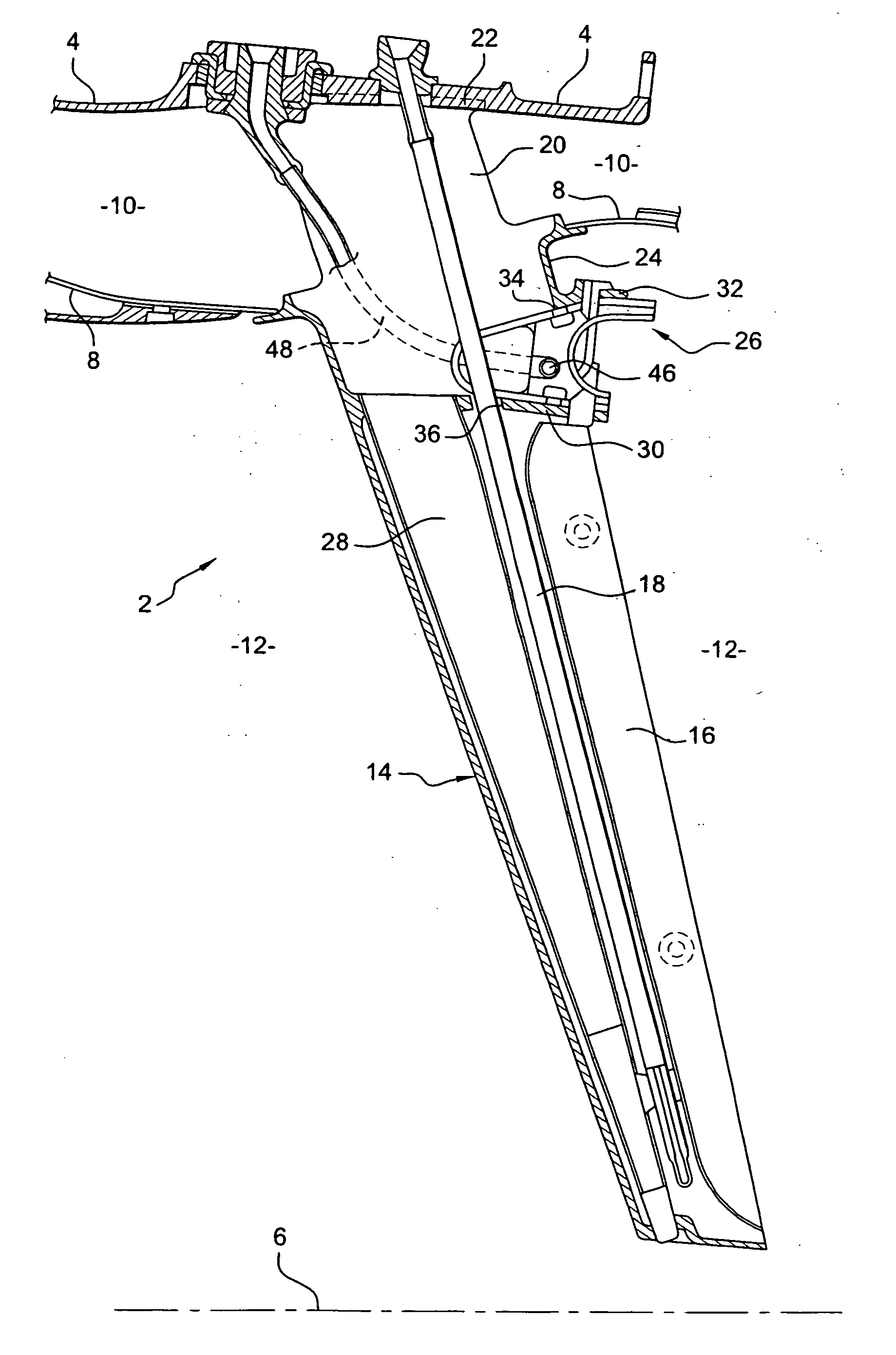
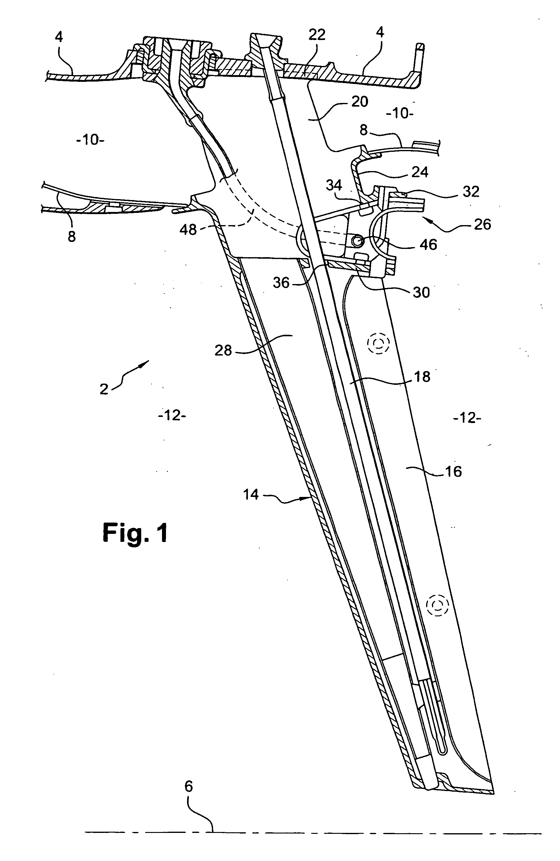
[0021] Reference is made initially to FIG. 1 which shows a portion of an after-burner chamber 2 of a bypass turbojet, the chamber being located downstream from the turbine of the turbojet.

[0022] The after-burner chamber 2 comprises a substantially cylindrical outer casing 4 of axis 6 and an inner cylindrical wall 8 coaxial with the outer casing 4, and co-operating therewith to define an annular space 10 extending from upstream to downstream, in which there flows the cold or secondary flow of the turbojet as generated by a fan at the upstream end of the turbojet and serving to increase thrust and to cool components of the turbojet.

[0023] The inner wall 8 defines an inner cylindrical space 12 extending from upstream to downstream in which there flows the hot or primary flow of the turbojet as constituted by the exhaust gas from the combustion chamber of the turbojet.

[0024] After-burning serves to increase the thrust of the turbojet and consists in injecting air and fuel into the pr...


PUM


Abstract

A device for feeding air and fuel to a burner ring in an after-burner chamber comprises a plurality of flame-holder arms extending radially about the axis of the chamber from an outer casing, a burner ring made up of ring sectors mounted substantially end to end on the flame-holder arms, and means for feeding air and fuel to the burner ring sectors, said means extending between the burner ring and the outer casing of the after-burner chamber inside the flame-holder arms.

Description

[0001] The present invention relates to feeding air and fuel to a burner ring in an after-burner chamber, in particular in a bypass turbojet. BACKGROUND OF THE INVENTION [0002] In general, the after-burner systems of turbojets comprise a plurality of flame-holder arms extending radially relative to the axis of the turbojet from an outer casing of an after-burner chamber into the hot primary flow formed by the combustion gas, each flame-holder arm containing a fuel feed duct which extends radially inside the arm from the outer casing. [0003] A burner ring is carried by the downstream portion of the flame-holder arms and extends either in the primary flow in the vicinity of the boundary between the primary flow and the cold secondary flow generated by the fan of the turbojet and flowing around the after-burner chamber, or else in the secondary flow itself. The ring may be made up of sectors whose facing ends are placed substantially end to end and are mounted on the flame-holder arms....

Claims


Application Information

Patent Timeline
Patent Type & Authority Applications(United States)
IPC IPC(8): F23R3/18F02K3/11F23R3/20
CPCF23R3/20F02K3/11
Inventor ROCHE, JACQUES ANDRE MICHELBUNEL, JACQUES MARCEL ARTHUR
Owner SN DETUDE & DE CONSTR DE MOTEURS DAVIATION S N E C M A
Why Eureka
Try Eureka