Systems, assemblies, and methods of reducing head loss in heating devices

a technology of heating device and head loss, applied in the direction of indirect heat exchangers, functional valve types, lighting and heating apparatus, etc., can solve the problems of no diverter valve positioned in the heater manifold, and achieve the effect of reducing head loss, less energy, and less erosion or corrosion of components

Active Publication Date: 2016-07-07
ZODIAC POOL SYST LLC
View PDF16 Cites 0 Cited by
  • Summary
  • Abstract
  • Description
  • Claims
  • Application Information

AI Technical Summary

Benefits of technology

[0007]The present invention provides a low-restriction chamber in a manifold of a heating device. When the heating device is inactive, water may be diverted through the low-restriction chamber for return to a recirculation system (or otherwise) so as to reduce head loss in the flowing water. By redirecting water from an inactive heating device to the low-restriction chamber, less energy may be necessary to circulate the water through the system. Additionally, by avoiding passing water through a heat exchanger when heating is not occurring, less erosion or corrosion of components of the heat exchanger occurs. Positioning the low-restriction chamber and by-pass apparatus within the manifold helps protect them from damage and should result in a less-costly by-pass system, as no separate external plumbing is required.
[0010]It thus is an optional, non-exclusive object of the present invention to provide systems, assemblies, and methods of reducing head loss in heating devices.
[0012]It is also an optional, non-exclusive object of the present invention to provide a repositionable gate for directing water flow within a low-restriction chamber, both of which may be placed within a heater housing so as to avoid need for external plumbing.

Problems solved by technology

Not all of the circulating pool water passes into the secondary coils, however; instead, some water continues through the circulation system unheated.
No other technique of causing all water to by-pass the heat exchanger when the heater is inactive is detailed in the Leniger patent, however, nor is any diverter valve positioned in a heater manifold.

Method used


Image

  • Systems, assemblies, and methods of reducing head loss in heating devices
  • Systems, assemblies, and methods of reducing head loss in heating devices
  • Systems, assemblies, and methods of reducing head loss in heating devices

Examples


Embodiment Construction

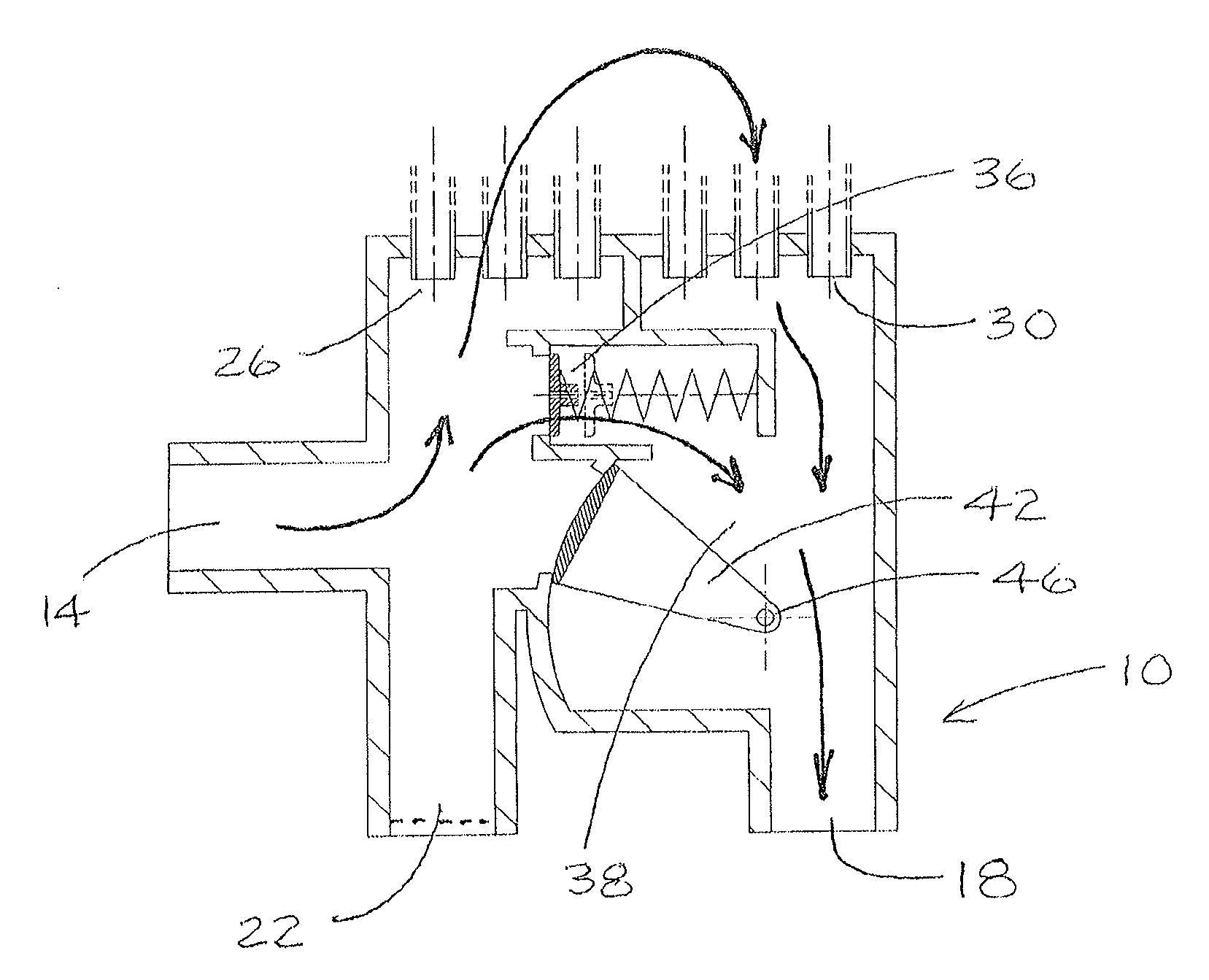
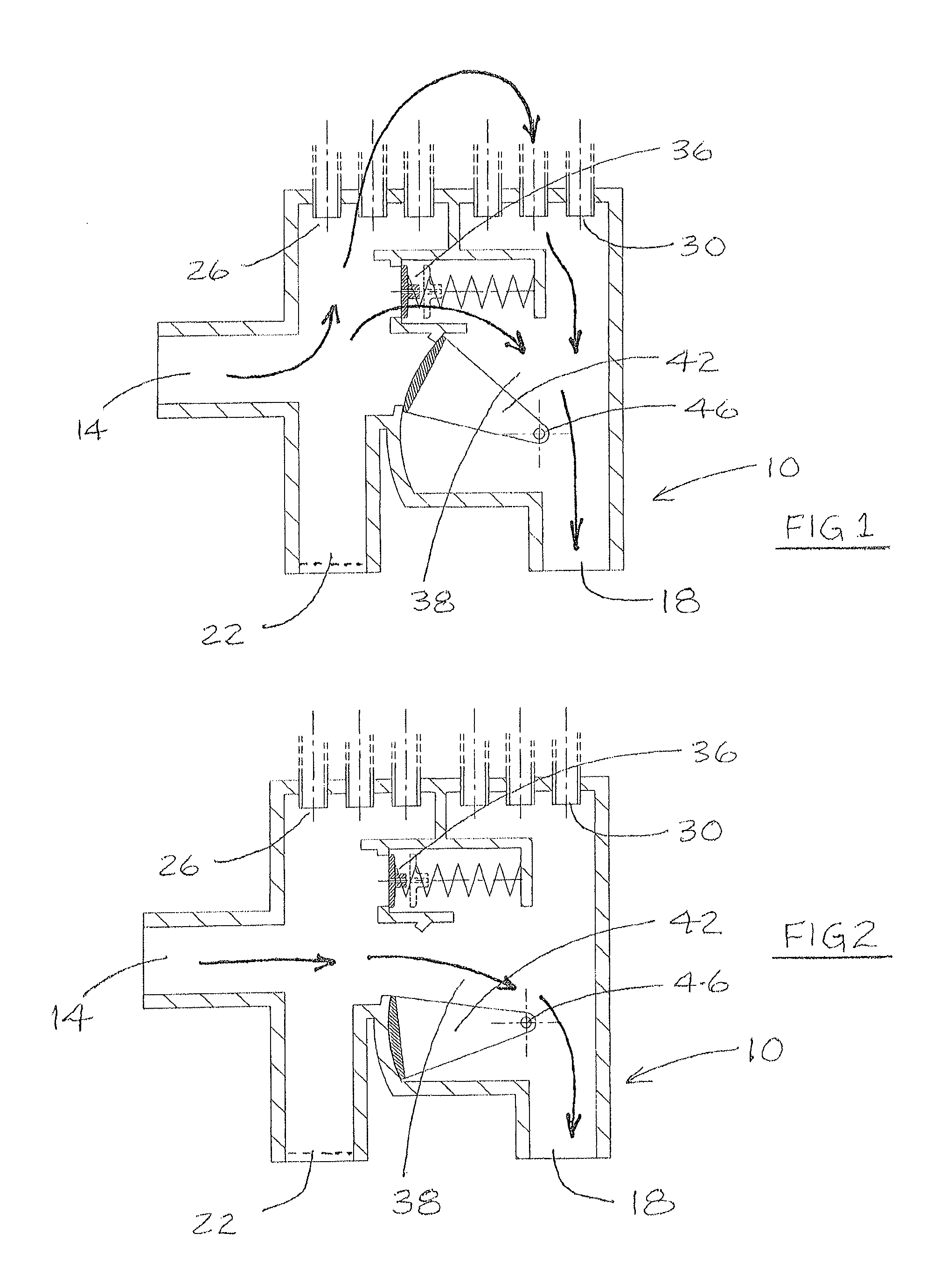
[0022]Illustrated in FIGS. 1-2 and 5 is exemplary manifold 10. Manifold 10 may include at least one inlet 14 and at least one outlet 18. Also shown in FIGS. 1-2 and 5 is optional second inlet 22. Depending on how manifold 10 is plumbed in a water circulation system, either of inlets 14 or 22 may be connected so as to receive circulating water. Typically the other of inlets 14 or 22 would be plugged, although conceivably both inlets 14 and 22 could be used simultaneously.

[0023]Included in manifold 10 may be plural openings 26 and 30. Openings 26 preferably, although not necessarily, are aligned, as preferably are openings 30. A corresponding set of openings 26 and 30 may function as inlet and outlet of an associated tube 34 of a heat exchanger or similar device. FIG. 5 shows six such tubes 34, although more or fewer tubes 34, or “tubes” of different shape, may be utilized instead. Also included in manifold 10 may be poppet valve assembly 36.

[0024]Shown especially in FIG. 2 is low-res...


PUM


Abstract

Low head loss systems are detailed. The systems may include chambers having low impedance to water flow therethrough and repositionable gates or other valves within the chambers. The valves may direct water as a function of whether an associated heating device is active. At least some gates may incorporate poppet valves or other high-flow by-passes.

Description

CROSS-REFERENCE TO RELATED APPLICATION[0001]This application claims the benefit of U.S. Provisional Patent Application Ser. No. 61 / 703,397, filed Sep. 20, 2012, and entitled “Low Head Loss Device for Swimming Pool Heaters or Other Applicable Equipment,” the entire contents of which application are incorporated herein by this reference.FIELD OF THE INVENTION[0002]This invention relates to flow by-pass systems and assemblies and methods of their use and more particularly, although not necessarily exclusively, to systems and assemblies within manifolds for allowing flowing water to by-pass heat exchangers or other components of swimming pool heaters when such heaters are inactive.BACKGROUND OF THE INVENTION[0003]U.S. Pat. No. 4,279,128 to Leniger describes an example of a heating system for recirculating water of a swimming pool. The system employs a heat pump to move heat-transfer fluid through primary coils of a heat exchanger while pool water circulates through secondary coils of th...

Claims


Application Information

Patent Timeline
Patent Type & Authority Applications(United States)
IPC IPC(8): E04H4/12
CPCE04H4/1245E04H4/129F16K11/076F28F27/02F28D1/0476F28D1/05325F28D7/06F28D7/08F28D7/1607F28F2250/06Y10T137/877F16K15/1848E04H4/14Y10T137/86726Y10T137/6416E04H4/1209Y10T137/87362
Inventor MASKELL, BRUCE WILLIAM
Owner ZODIAC POOL SYST LLC
Why Eureka
Try Eureka