

Device for the mixing of fluids
a fluid mixing and fluid technology, applied in beverage vessels, liquid dispensing, packaging, etc., can solve the problems of affecting consumer appreciation, not allowing precise and rapid feedback control of fluid flow rate,
Active Publication Date: 2020-11-10
MARCHETTI
View PDF5 Cites 0 Cited by
- Summary
- Abstract
- Description
- Claims
- Application Information
AI Technical Summary
Benefits of technology
The device achieves precise and continuous control of fluid flow rates, maintaining the desired mixing ratio under varying conditions, reducing turbulences and residue formation, and ensuring consistent flavor reproducibility.
Problems solved by technology
They do not in fact allow a precise and rapid feedback control of the fluid flow rates.
More in detail, the flow rate control performed by adjusting the opening time of the relative valves does not allow, also because of the response times of the relevant shutters, to carry out an effective feedback control of the flow rate of the fluids.
This limit of the devices of known type generally translates into low reproducibility over time of the flavor of the dispensed drinks, which can therefore affect appreciation by consumers.
Generally, the bigger the operating pressure and the viscosity of the dispensed fluids, the more evident this drawback is.
Method used
View moreImage
Smart ImageViewing Examples

Examples
first embodiment
[0036]FIGS. 6 and 7 are sectional views, on an enlarged scale, illustrating the valve means in the device according to the invention;
second embodiment
[0037]FIGS. 8 and 9 are axonometric views, on an enlarged scale and partially broken, illustrating the valve means present in the device according to the invention;
[0038]FIG. 10 is a diagram illustrating the control logic of the device according to the invention;
[0039]FIG. 11 is a graph illustrating a possible sequence of the opening and closure cycles of the valve means of the device according to the invention.
Login to View More PUM
 Abstract
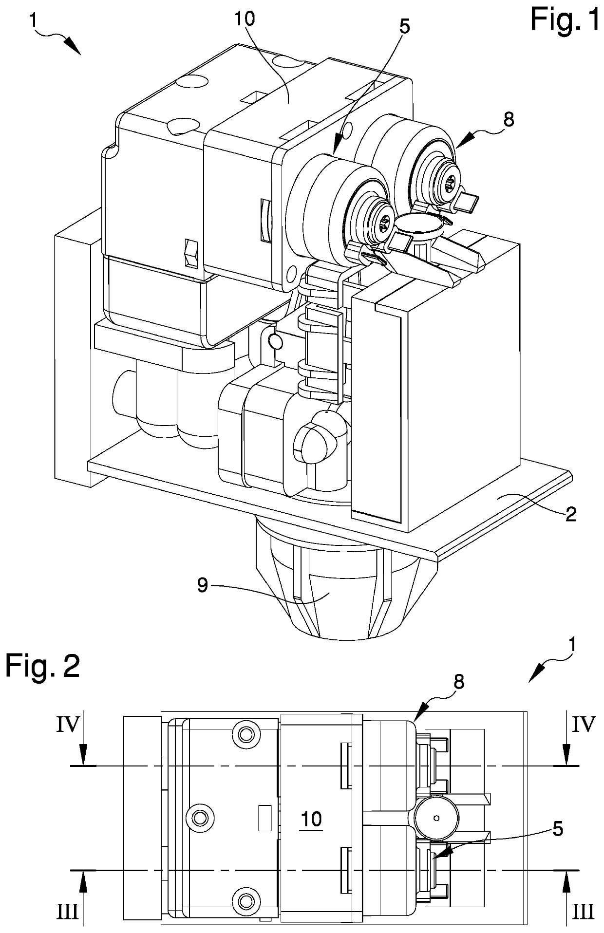
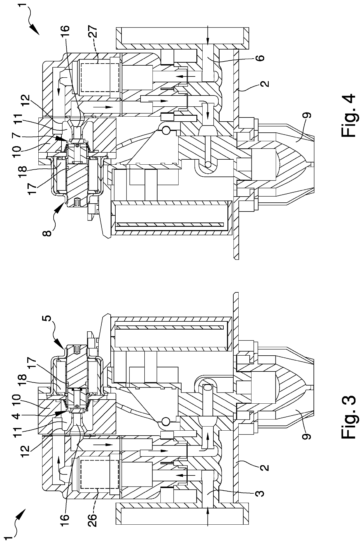
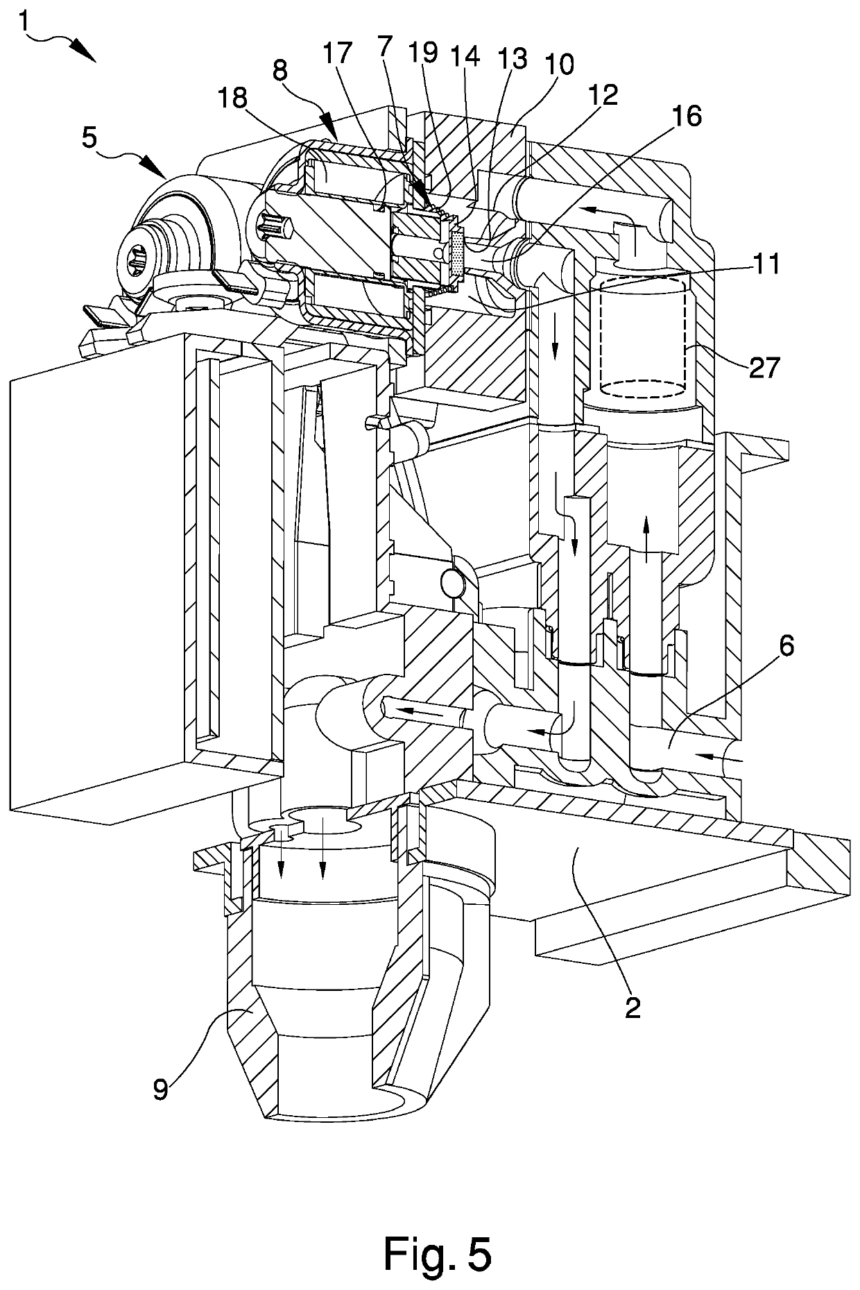
The device (1) for the mixing of fluids comprises:—a first supply line (3) of a first fluid along which first valve means (4) are arranged, there being provided first control means (5) able to command the opening / closure of the first valve means (4); —at least a second supply line (6) of a second fluid along which second valve means (7) are arranged, there being provided second control means (8) able to command the opening / closure of the second valve means (7); —driving means (20) of the control means (5, 8) which comprise generation means (21, 22) of an impulsive driving signal (23) by pulses able to open the first valve means (4) and / or the second valve means (7) for an impulsive opening time (T-on) and to close the first valve means (4) and / or the second valve means (7) for an impulsive closure time (T-off), wherein the ratio between the impulsive opening time (T-on) and the impulsive closure time (T-off) for each pulse is constant and the pulses have a variable repetition frequency.
Description
RELATED APPLICATIONS[0001]The present invention is the U.S. National Phase of, and claims priority to, International Patent Application No. PCT / IB2016 / 054691 filed Aug. 3, 2016, which claims priority to Italian Patent Application Number UB2015A003021 filed Aug. 7, 2015; all of which are incorporated herein by reference in their entireties.TECHNICAL FIELD[0002]The present invention relates to a device for the mixing of fluids.BACKGROUND ART[0003]To date several types of device are known for the mixing of fluids, e.g., used to prepare drinks, where syrup or juice concentrate has to be mixed with a diluent, e.g., water, in order to obtain the desired drink.[0004]These devices generally have a first supply line of a first fluid, e.g., water, along which are arranged first valve means adapted to control the flow rate of the first fluid itself, a second supply line of a second fluid, e.g., syrup or juice, along which are arranged second valve means adapted to control the flow rate of the ...
Claims
Login to View More Application Information
Patent Timeline
 Patent Type & AuthorityPatents(United States)
IPC IPC(8): B67D1/00B67D1/12
CPCB67D1/1295B67D1/1293B67D1/0085B67D1/0036B67D1/0044A47J31/00A47J31/40A47J31/41B67D1/12
InventorALBERINI, VILIAMROLLI, STEFANO
OwnerMARCHETTI