Pressure gauge glow plug

a technology of glow plugs and pressure gauges, applied in the direction of lighting and heating equipment, instruments, machines/engines, etc., can solve problems such as measurement errors and change of properties

Inactive Publication Date: 2005-11-17
BERU AG DE
View PDF3 Cites 40 Cited by
  • Summary
  • Abstract
  • Description
  • Claims
  • Application Information

AI Technical Summary

Problems solved by technology

In a pressure gauge glow plug of this type, not only is the pressure produced in the cylinder relayed via the heating element to the pressure sensor, but also mechanical forces caused by temperature oscillations or thermal...

Method used


Image

  • Pressure gauge glow plug
  • Pressure gauge glow plug
  • Pressure gauge glow plug

Examples


Embodiment Construction

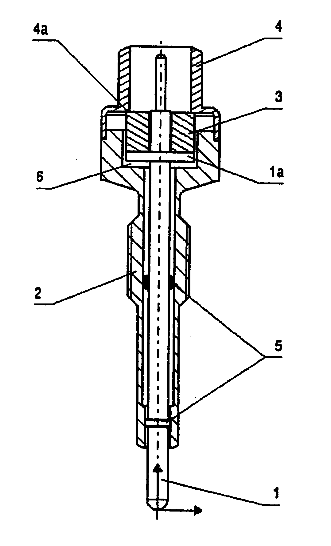
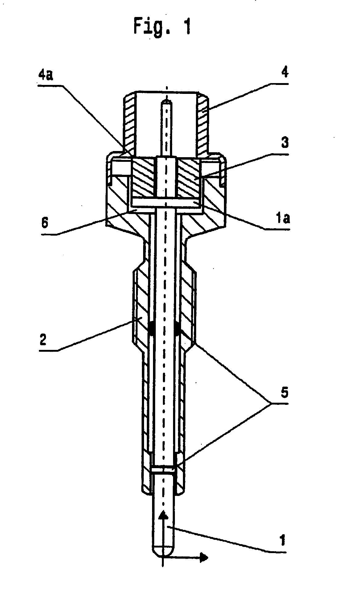
[0014] The exemplary embodiment of the pressure gauge glow plug according to the present invention shown in FIG. 1 has a plug body or housing 2, in which a heating element 1 is positioned so that it projects, on the combustion chamber side, from the plug body 2. The plug body 2 is designed for inserted into a cylinder of a diesel engine.

[0015] A pressure sensor 3 is positioned under pretension between the heating element 1 and the plug body 2 in such a way that the pressure sensor 3 experiences the pressure existing in the combustion chamber of the cylinder in which it has been inserted. For this purpose, the heating element 1 is positioned so that it may be displaced by sliding in the axial direction in the plug element 2, so that it transmits the pressure in the combustion chamber of the cylinder to the pressure sensor 3.

[0016] As is illustrated in detail in FIG. 1, the pressure sensor 3 is positioned on a heating element support 1a, which is fixedly bonded to the heating elemen...


PUM


Abstract

A pressure gauge glow plug for a diesel engine having a plug body, a heating element, and a pressure sensor, which is positioned under pretension between the heating element and the plug body in such a way that the pressure sensor experiences the pressure existing in the combustion chamber of the cylinder in which it is inserted. The heating element is positioned so that it may be slid in an axial direction in the plug body and transmits the pressure in the combustion chamber of the cylinder to the pressure sensor. The pressure sensor is positioned on a heating element support that is permanently bonded to the heating element in a cap that permanently bonded to the plug body. The heating element support and pressure sensor form a unit that has axial play in the interior of the cap.

Description

BACKGROUND OF THE INVENTION [0001] 1. Field of Invention [0002] The present invention relates to a pressure gauge glow plug for a diesel engine having a plug body for insertion into a cylinder of the diesel engine, a heating element which is positioned in the plug body, and a pressure sensor, which is positioned, under pretension, between the heating element and the plug body in such a way that the pressure sensor experiences the pressure existing in the combustion chamber of the cylinder, which is transmitted from the heating element. [0003] 2. Description of Related Art [0004] A pressure gauge glow plug of this type is known from European Patent Application EP 1 096 141 A3 and corresponding U.S. Pat. No. 6,539,787. [0005] In this known pressure gauge glow plug, the plug body and the heating element are rigidly bonded to one another on the combustion chamber side and the plug body has such a strength that it may radially deform elastically when a pressure is applied to it. The pres...

Claims


Application Information

Patent Timeline
IPC IPC(8): F02P19/00F02D35/00F23Q7/00G01L23/22
CPCF02P19/028F23Q2007/002G01L23/22F23Q7/001F02P19/00F02P19/02
Inventor HEINZELMANN, STEFANPECHHOLD, FRANKMARTO, ARNO
Owner BERU AG DE
Why Eureka
Try Eureka