Cover opening and closing device
a technology for opening and closing devices and covers, which is applied in the field of cover opening and closing devices, can solve the problems of lowering quality, complex structure, and the risk that the driver or passenger might push a wrong button, and achieves the effects of reducing the space for the button placement, improving the external design characteristics, and simple engagement devices
- Summary
- Abstract
- Description
- Claims
- Application Information
AI Technical Summary
Benefits of technology
Problems solved by technology
Method used
Image
Examples
first embodiment
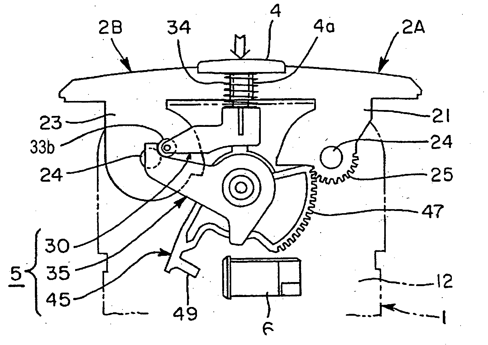
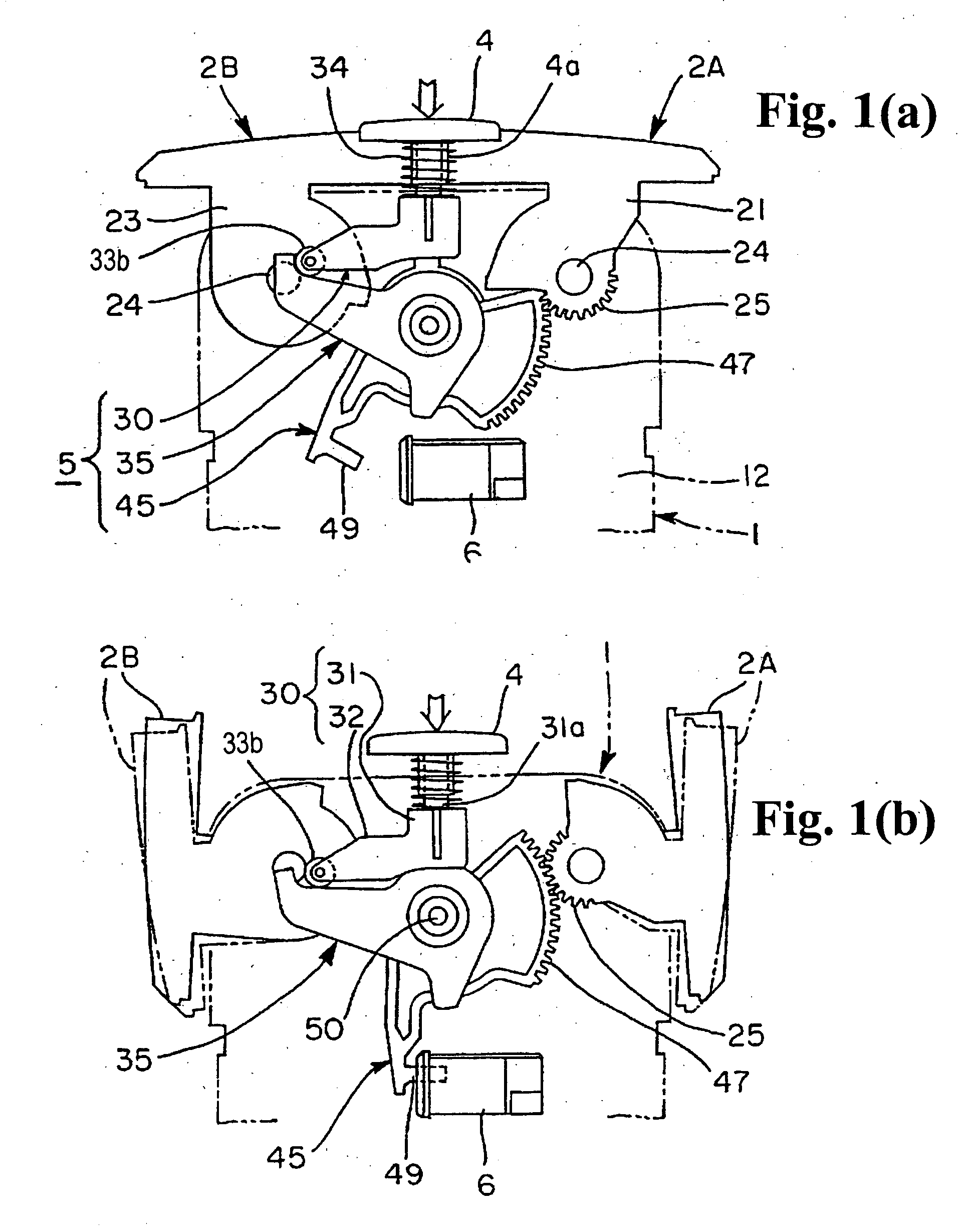
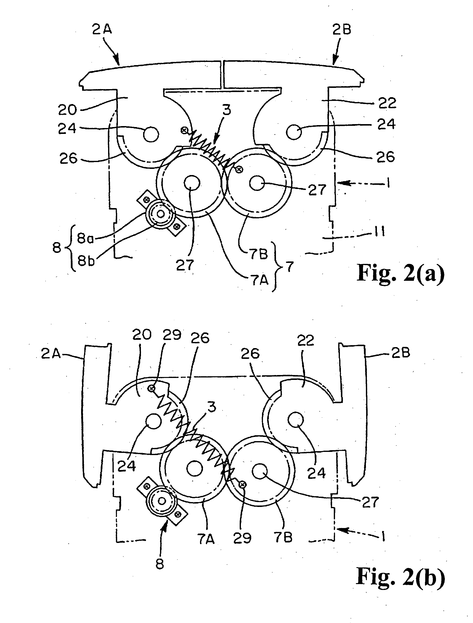
[0048] The cover opening and closing device of the first embodiment shown in FIGS. 1(a) and 1(b) to FIGS. 6(a) and 6(b), just as in Patent Document 1, is made as a mechanism for opening and closing an upper opening of a main body 1 which is housed inside a rectangular box-shaped housing part formed by an automobile console box. The apparatus or mechanism comprises a coil spring 3 as a forcing device, an operation button 4, a switching device 5, a latch 6, a power transmitting device 7, and a damper device 8. The switching device 5 is constituted by a cam 35 which is rocked or rotated by a movable body 30 by a push operation of the button 4, an acceleration gear 45 which is linked to the cam 35 by a force amplifying gear mechanism 40, and a catching claw 49 which is provided on a part of the acceleration gear 45, and the like.
[0049] The main body 1 is partitioned by front and rear walls 11 and 12, a bottom wall 13, and reinforcing pieces or projecting walls 14 provided on both sides...
modified example 1
[0064] The modified example shown in FIGS. 7(a) and 7(b) and FIGS. 8(a) and 8(b) switches one cover body 2 to rotate between the closed position and the open position using the cover opening and closing device. The structure comprises as constituent members: a coil spring 3 as a forcing device which normally forces the cover body 2 pivotally supported on the main body 1 toward the direction of the closed position; a single push operation button 4 which is provided on the main body 1 or a border member 10 for the main body; a switching device 5 which has a cam 35 placed opposite to the button 4 and an acceleration gear 45 being linked to the cam 35 and engaging a gear part 25 provided on the cover body 2 and a catching claw 49 provided on the acceleration gear 45, and switches the cover body 2 from the closed position to the open position in opposition to the force of the coil spring 3 by the cam 35 and the acceleration gear 45 by the push operation of the button 4; and a latch 6 whi...
modified example 2
[0067] When the latch 6 which catches and releases the catching claw 49 is a push-push catching mechanism, as shown in FIG. 1(b), the cover body moves slightly toward the open direction when the holding of the catching claw 49 is released by the push operation of the button 4. The modified example shown in FIG. 9 to FIGS. 14(a) and 14(b) eliminates such a slight movement of the cover. Structurally, a bracket 9A (corresponding to the bracket 9) has an arm 51 and a trace pin 53 protruding on the free end of the arm 51. Inside the vertical part 31 of the movable body 30, a sliding body 55 in which a cam groove 56 is formed; a frame member 57 which is built into the vertical part 31 in a state of retaining the sliding body 55; a lock member 59 which is built in below inside the frame 57; a coil spring 58a which forces the frame member 57 upwardly; and a coil spring 58b which forces the lock member 59 toward the direction of protruding from the frame member 57 are built in. They are feat...
PUM
 Abstract
Description
Claims
Application Information
 - R&D
- Intellectual Property
- Life Sciences
- Materials
- Tech Scout
- Unparalleled Data Quality
- Higher Quality Content
- 60% Fewer Hallucinations
Browse by: Latest US Patents, China's latest patents, Technical Efficacy Thesaurus, Application Domain, Technology Topic, Popular Technical Reports.
© 2025 PatSnap. All rights reserved.Legal|Privacy policy|Modern Slavery Act Transparency Statement|Sitemap|About US| Contact US: help@patsnap.com


