

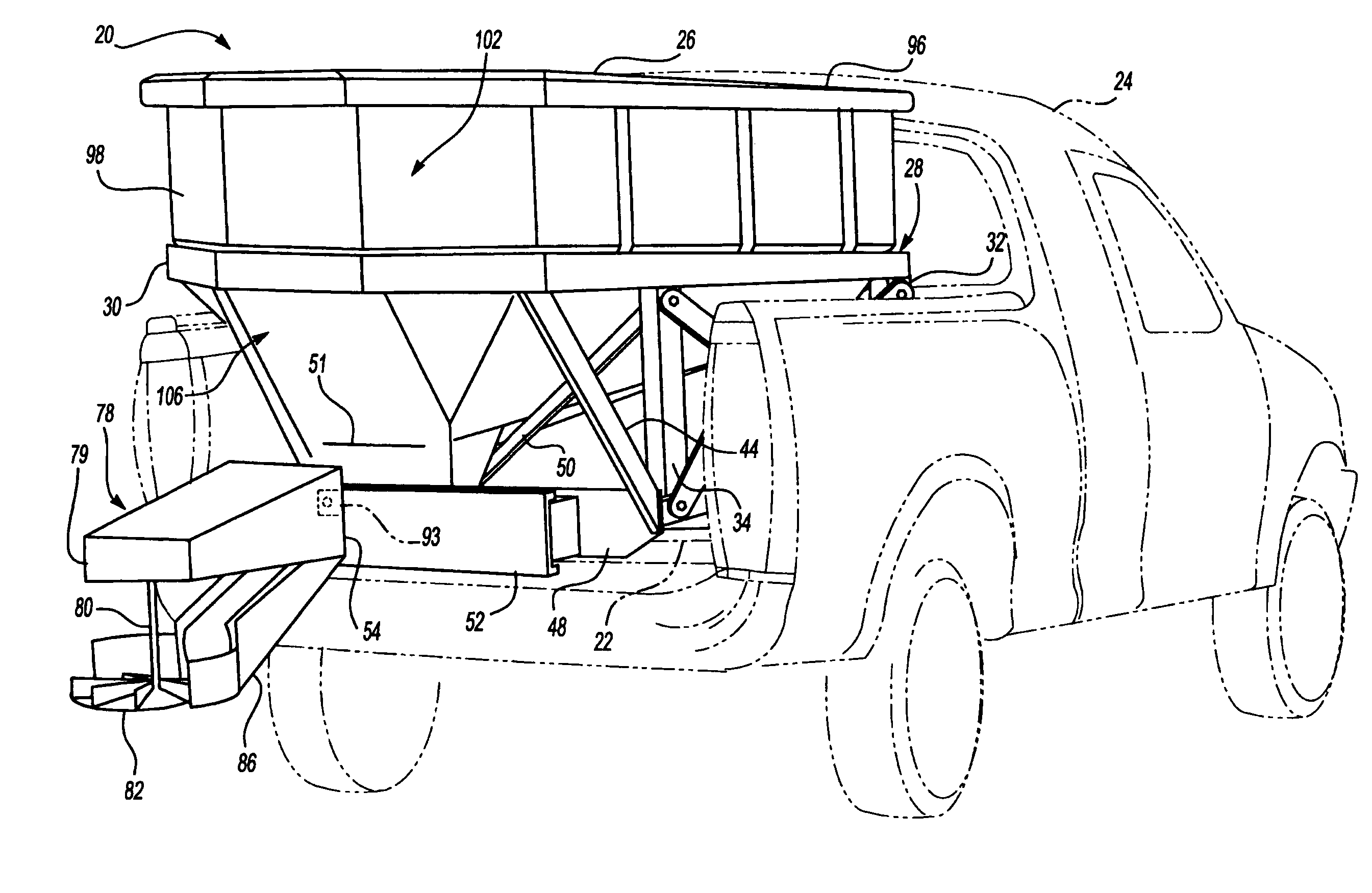
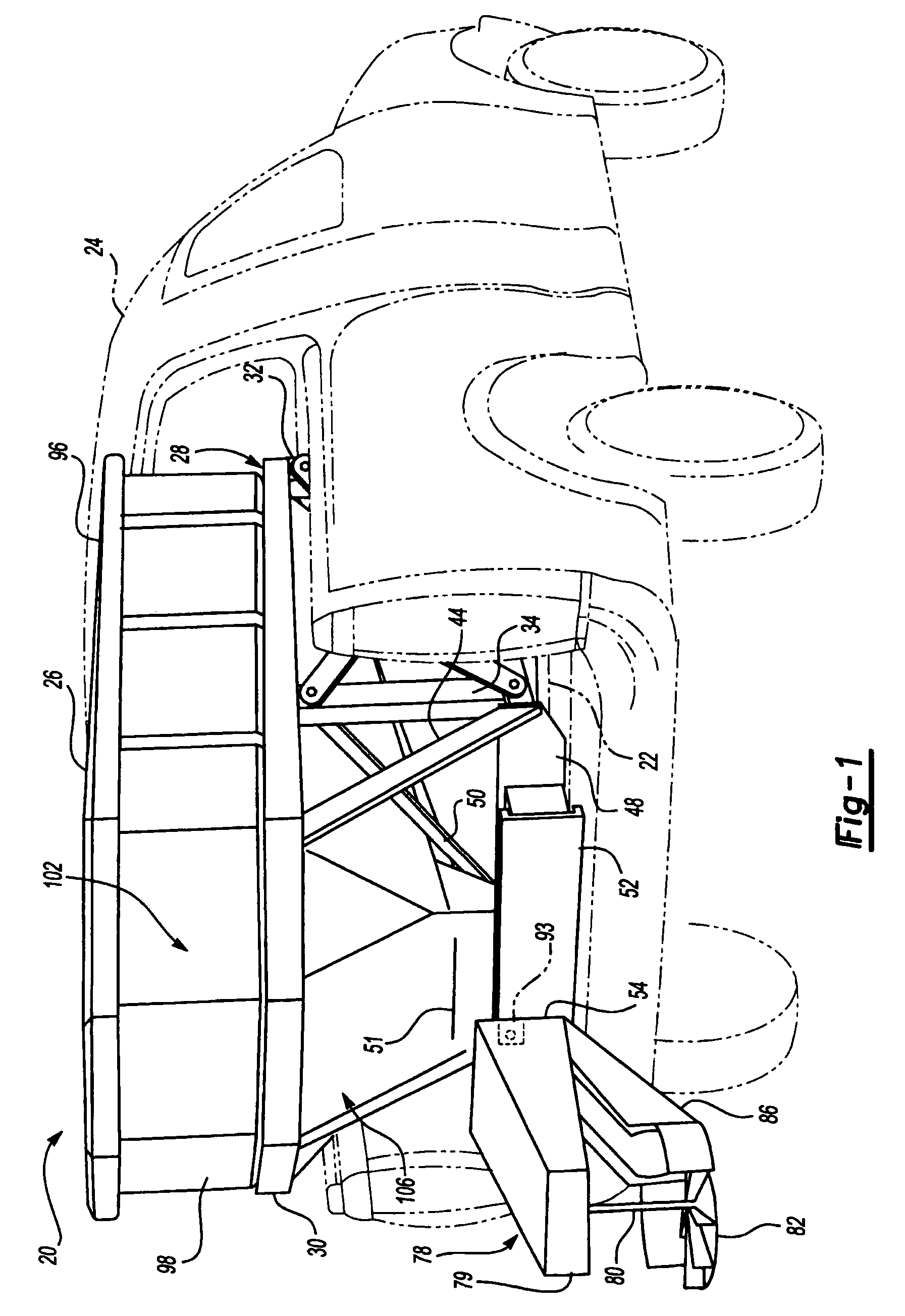
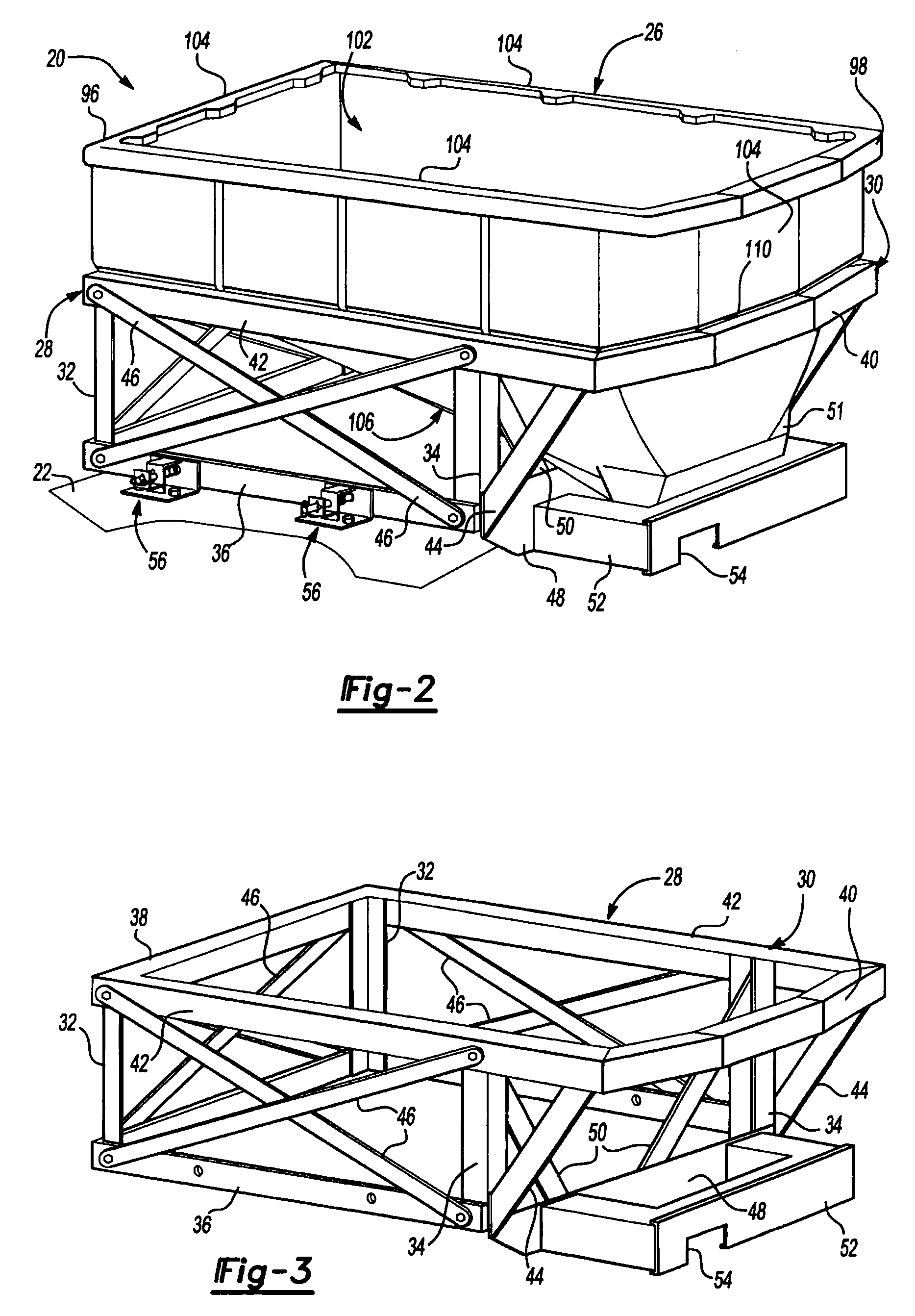
Truck bed mounted spreader
a spreader and truck bed technology, applied in the field of spreaders, can solve the problems of not having a large capacity hopper, 5 hours to remove from the back of the vehicle, and none of the related art spreaders provide for it, and achieve the effects of convenient removal, light weight and more responsiveness
- Summary
- Abstract
- Description
- Claims
- Application Information
AI Technical Summary
Benefits of technology
Problems solved by technology
Method used
Image

Examples
second embodiment
[0064]FIG. 18 is a perspective side view of the spreader assembly 220 removed from the bed 22 of the truck 24. In the second embodiment, both the hopper 226 and the frame 228 are formed from a thermoplastic material and the hopper 226 and the frame 228 are integrally connected to one another such that the hopper 226 and the frame 228 are unitary. It is to be appreciated by those of ordinary skill in the art that the frame 228 may be formed separate from the hopper 226 and then the frame 228 is secured to the hopper 226 to form the unitary structure. For example, since both the frame 228 and the hopper 226 are formed of thermoplastic materials, the frame 228 and the hopper 226 may be hot melted together or secured together with an adhesive that causes either chemical or mechanical bonding therebetween. Alternatively, the hopper 226 and the frame 228 may be formed from a continuous and homogenous material. For example, both the hopper 226 and the frame 228 could be formed in a single ...
third embodiment
[0071] Referring back to FIG. 25, a pair of front posts 432 extend upwardly from the base 435 at the front end 437 and a pair of rear posts 434 extend upwardly from the base 435 at the rear end 439. The posts 432, 434 engage the hopper 426 and support the hopper 426 in the bed 22 of the truck 24. It is to be appreciated by one of ordinary skill in the art that more than two pairs of posts may be used to support the hopper 426. In the third embodiment, the base 435 and the posts 432, 434 are each formed from a thermoplastic material. For example, the base 435 and the posts 432, 434 may be integrally formed as a unitary structure for supporting the removable hopper 426. FIG. 26 is a side view of the frame 428 having the posts 431 engaging and supporting the hopper 426.
[0072] Referring again to FIG. 25, each of the posts 431 also includes an interlock 446 for engaging the hopper 426 to limit movement during operation. The interlock 446 may directly engage the side of the hopper 426 to ...
PUM
 Abstract
Description
Claims
Application Information