Information processing method and apparatus for finding position and orientation of targeted object

a technology for information processing and object position, applied in the direction of diagnostic recording/measuring, instruments, applications, etc., can solve the problems of insufficient accuracy and stability of obtained solutions, inability to find solutions, and difficulty in identifying indices

Inactive Publication Date: 2005-11-17
CANON KK
View PDF2 Cites 38 Cited by
  • Summary
  • Abstract
  • Description
  • Claims
  • Application Information

AI Technical Summary

Problems solved by technology

Similarly, in the case of the optical see-through, the problem of registration in mixed reality sense concludes as a problem of finding, in a scene, the position and orientation of the display or the observer's viewpoint.
However, in the above methods of the related art, in a situation in which a subjective viewpoint image does not include image information sufficient for realizing stable registration, for example, when indices locally existing in a portion of an image are observed, and when only three indices are observed and index detection includes an error, accuracy and stability of an obtained solution may become insufficient.
In addition, when the number of indices observed is not greater than two, no solution can be found.
This causes problems in that it is difficult to identify indices and in that the real space image is deformed.
In addition, there is a problem in that, in a situation in which images of indices on a subjective viewpoint image are covered with an observer's hand, registration is completely impossible.

Method used


Image

  • Information processing method and apparatus for finding position and orientation of targeted object
  • Information processing method and apparatus for finding position and orientation of targeted object
  • Information processing method and apparatus for finding position and orientation of targeted object

Examples


first embodiment

[0030] A position-and-orientation measuring apparatus according to a first embodiment of the present invention measures the position and orientation of an arbitrary targeted object to be measured. The position-and-orientation measuring apparatus according to the embodiment and a position-and-orientation measuring method therefor are described below.

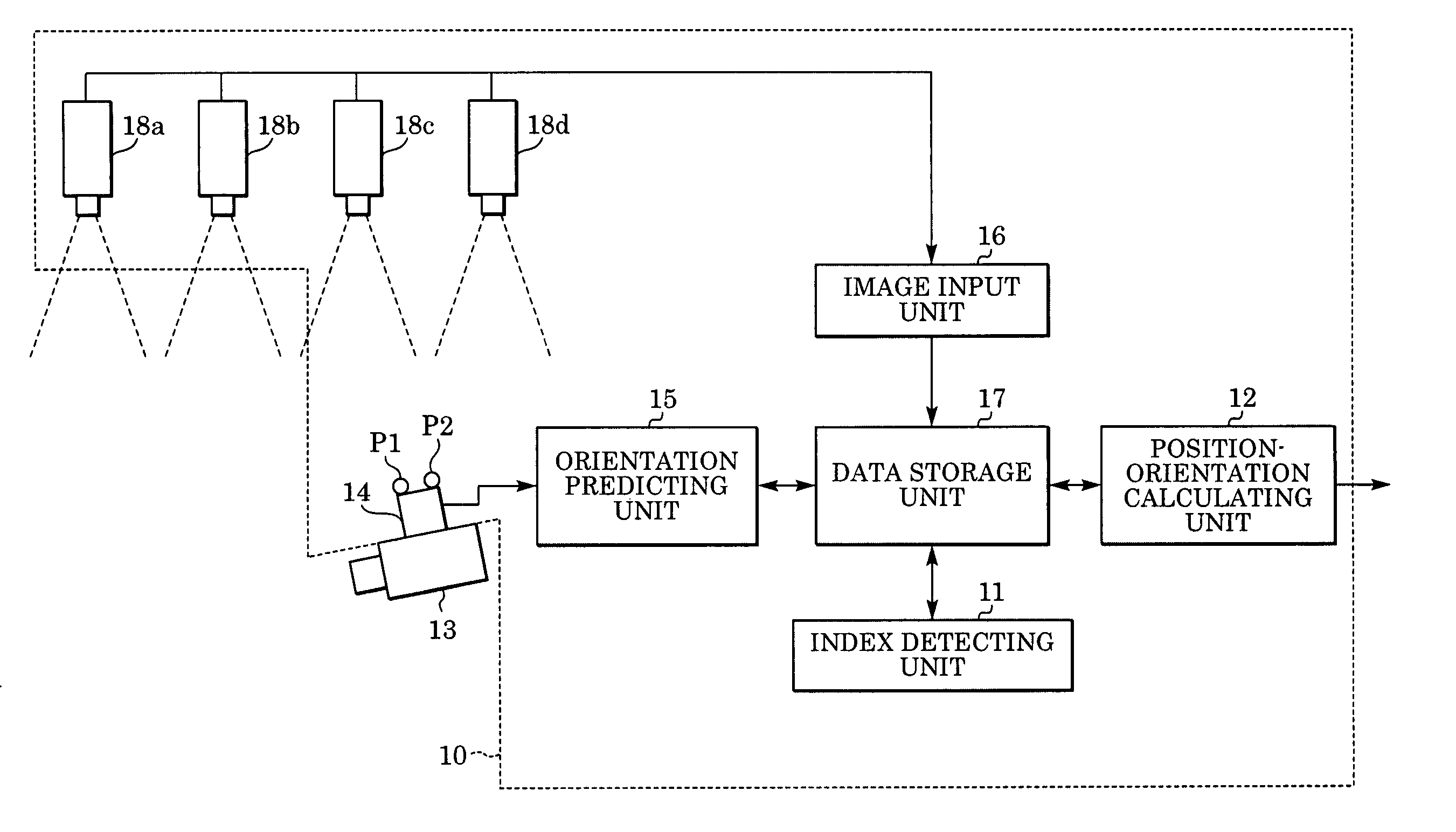
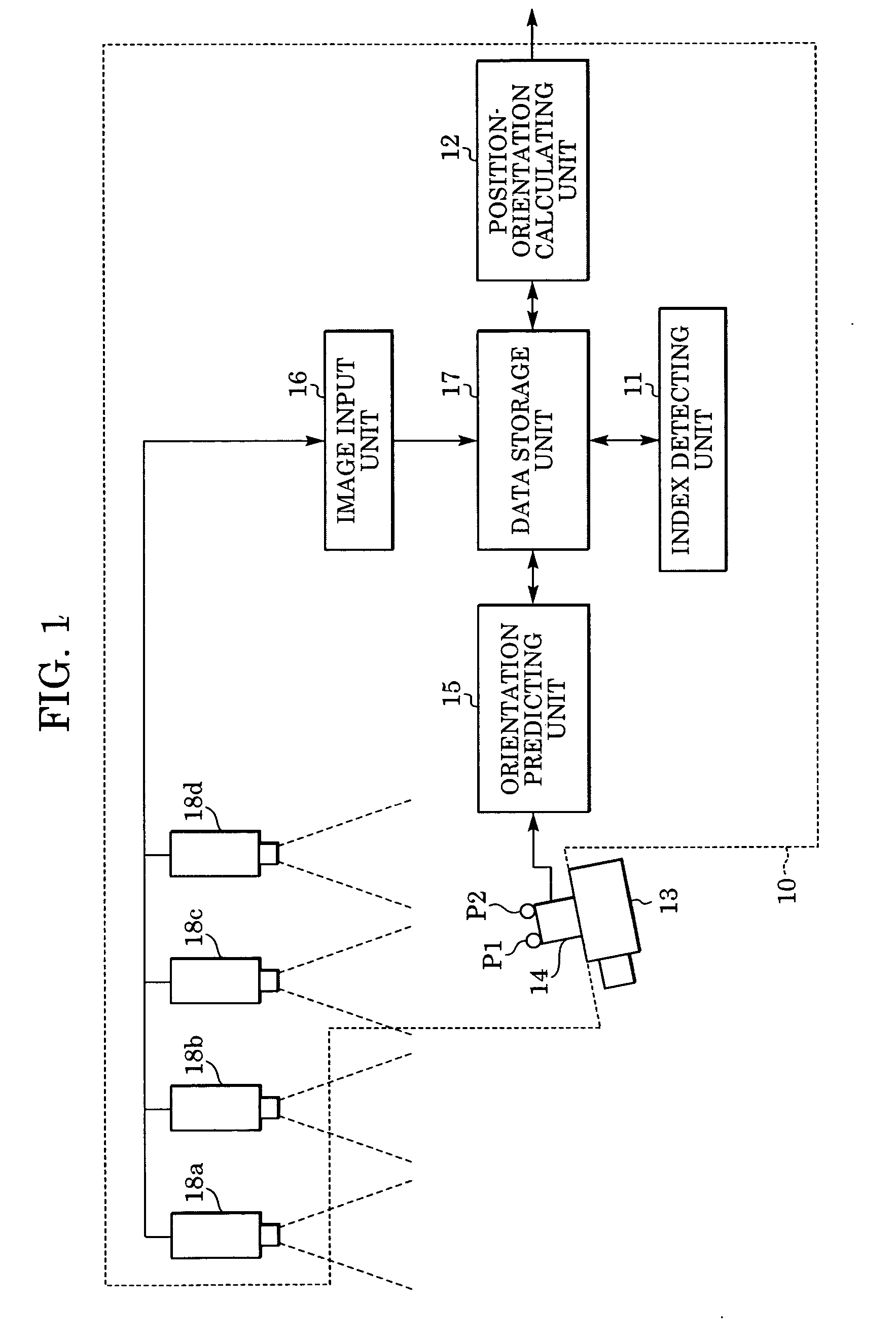
[0031]FIG. 1 shows the configuration of a position-and-orientation measuring apparatus 10 according to the first embodiment. As shown in FIG. 1, the position-and-orientation measuring apparatus 10 includes bird's-eye view cameras 18a, 18b, 18c, and 18d, an image input unit 16, a data storage unit 17, an index detecting unit 11, an orientation sensor 14, an orientation predicting unit 15, and a position-orientation calculating unit 12. The position-and-orientation measuring apparatus 10 is connected to a targeted object 13 to be measured.

[0032] At a plurality of positions on the orientation sensor 14 and / or the targeted object 13, indice...

second embodiment

[0101] A position-and-orientation measuring apparatus according to a second embodiment of the present invention measures the position and orientation of an imaging device. The position-and-orientation measuring apparatus according to the second embodiment and a position-and-orientation measuring method therefor are described below.

[0102]FIG. 6 shows the configuration of the position-and-orientation measuring apparatus according to the second embodiment. As shown in FIG. 6, the position-and-orientation measuring apparatus 100 includes bird's-eye view cameras 180a, 180b, 180c, and 180d, an image input unit 160, a data storage unit 170, an index detecting unit 110, an orientation sensor 140, an orientation predicting unit 150, and a position-orientation calculating unit 120. The position-and-orientation measuring apparatus 100 is connected to an imaging device 130.

[0103] At a plurality of positions in a real space, a plurality of indices Qk (k=1, . . . , KQ) (hereinafter referred to ...

first modification

of Second Embodiment

[0145] The second embodiment is intended to measure the position and orientation of an imaging device that moves in a space. Unlike the second embodiment, a position-and-orientation measuring apparatus according to a first modification of the second embodiment is intended to measure the position and orientation of an arbitrary targeted object. This position-and-orientation measuring apparatus is configured by adding a subjective viewpoint camera to the position-and-orientation measuring apparatus according to the second embodiment. The position-and-orientation measuring apparatus according to the first modification of the second embodiment and a method therefor are described below.

[0146]FIG. 9 is a block diagram showing the configuration of the position-and-orientation measuring apparatus (denoted by reference numeral 500) according to the first modification of the second embodiment. As shown in FIG. 9, the position-and-orientation measuring apparatus 500 includ...


PUM


Abstract

In an information processing method, an orientation sensor is mounted on a targeted object to be measured, and bird's-eye view cameras for capturing images of the targeted object are fixedly installed. From the images captured by the bird's-eye view cameras, an index detecting unit detects indices mounted on the orientation sensor. A measured orientation value from the orientation sensor is input to an orientation predicting unit, and the orientation predicting unit predicts the present orientation of the targeted object based on an azimuth-drift-error correction value. A position-orientation calculating unit uses the image coordinates of the detected indices to calculate the position of the imaging device and an update value of the azimuth-drift-error correction value, which are unknown parameters. From the obtained parameters, the position-orientation calculating unit finds and outputs the position and orientation of the targeted object.

Description

BACKGROUND OF THE INVENTION [0001] 1. Field of the Invention [0002] The present invention relates to an apparatus and method for measuring the position and orientation of an object. [0003] 2. Description of the Related Art [0004] Recently, research concerning mixed reality for the purpose of seamless linkage between a real space and a virtual space has been actively conducted. An image display apparatus for displaying mixed reality is realized by so-called “video see-through” in which a virtual space image (e.g., a virtual object drawn by computer graphics, text information, etc.), generated in response to the position and orientation of an imaging device such as a video camera, is drawn so as to be superimposed on a real space image captured by the imaging device, whereby a superimposition image is displayed. [0005] In addition, the image display apparatus can also be realized by so-called “optical see-through” in which a virtual space image, generated in response to the position a...

Claims


Application Information

Patent Timeline
Patent Type & Authority Applications(United States)
IPC IPC(8): G06T7/00
CPCG06T7/0044G06T7/0028G06T7/33G06T7/74
Inventor SATOH, KIYOHIDEUCHIYAMA, SHINJIENDO, TAKAAKISUZUKI, MASAHIRO
Owner CANON KK
Why Eureka
Try Eureka