Velocity determination of the near-surface layers in the earth using exploration 2D or 3D seismic data

a technology of seismic data and near-surface layers, which is applied in the direction of seismology, instruments, geological measurements, etc., can solve the problems of false time structure (static-correction errors), lack of velocity information, and distortion of reflection-time images

Inactive Publication Date: 2005-11-17
WEST MICHAEL PATRICK
View PDF3 Cites 49 Cited by
  • Summary
  • Abstract
  • Description
  • Claims
  • Application Information

AI Technical Summary

Problems solved by technology

It is well-known that false time-structure (static-correction errors) can exist on most land, shallow marine (and even conventional marine) seismic 2D and 3D data.
This is due to the fact that large lateral velocity variations exist in the near-surface layers of the earth which cause travel-time errors which distort the reflection-time image of the subsurface reflectors below.
Refraction statics and statics created from Tomographic models can reduce the problem to some degree but both methods suffer from the lack of velocity information in this near-surface layer.
Velocity information is sometimes incorporated from drilled “uphole” survey information, but this information is usually on the order of 1 or 2 kilometers spatial intervals at best which is not small enough spatial sampling to eliminate static correction errors.
Depth migrated data can also suffer from an inaccurate velocity model of the near-surface layers.
The false time or depth structures left in the processed 2D or 3D seismic sections can lead to misinterpretation of hydrocarbon prospects and possibly to costly errors in oil and gas well placement sometimes costing millions of dollars.

Method used


Image

  • Velocity determination of the near-surface layers in the earth using exploration 2D or 3D seismic data
  • Velocity determination of the near-surface layers in the earth using exploration 2D or 3D seismic data
  • Velocity determination of the near-surface layers in the earth using exploration 2D or 3D seismic data

Examples


Embodiment Construction

[0015] It is the intention of this invention to provide an estimate of the near-surface velocity variations and therefore a velocity field that can be used in any time-correction or depth-correction method to alleviate the problems outlined above.

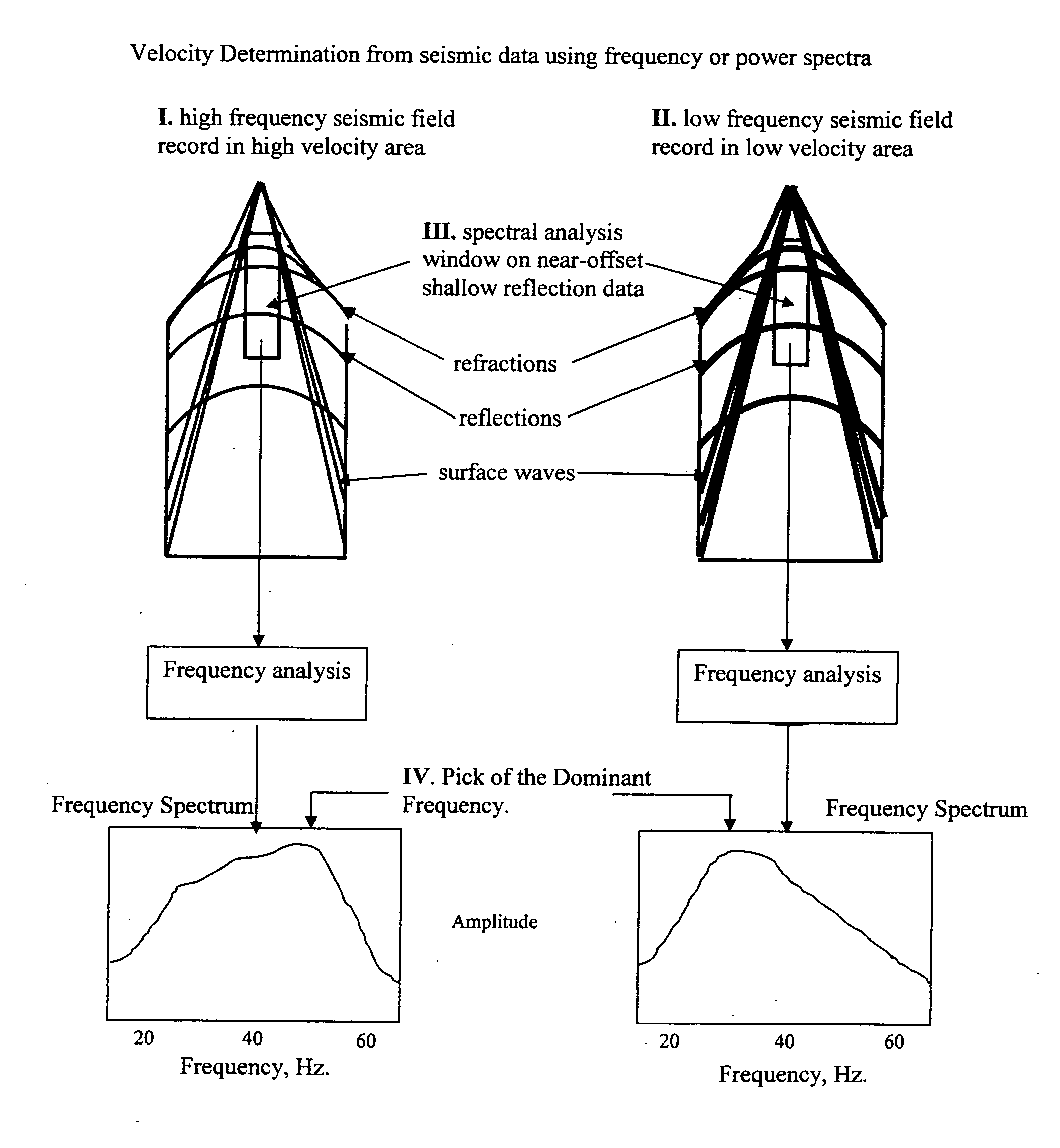
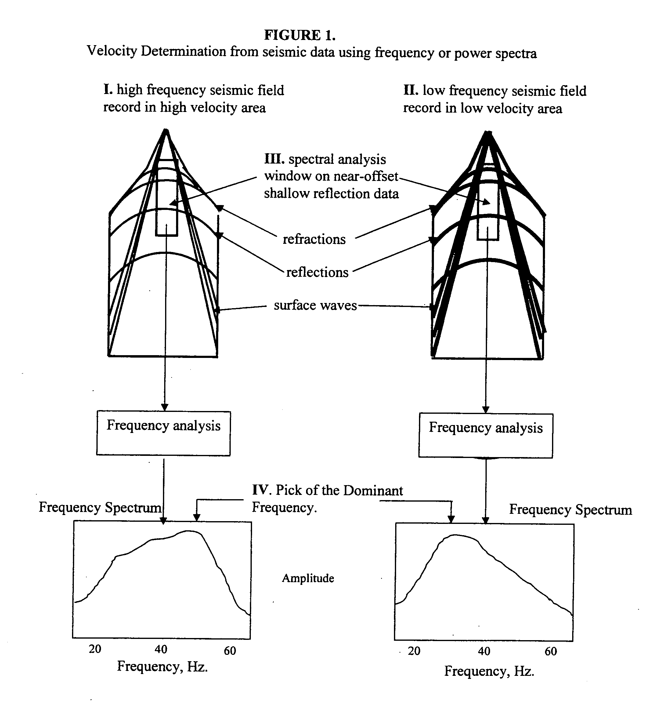
[0016] Near-surface velocity estimation using frequency spectra [0017] estimate the frequency content of unprocessed field records for a given analysis window (FIG. 1, element III.) using either averaged frequency spectra or averaged power spectra [0018] make a relative measure or “pick” of the dominant frequency peak of the spectrum or of the power spectrum.(FIG. 1, element IV.) [0019] save and record this dataset of measured “picks” for each surface location [0020] determine an estimated minimum near-surface velocity value and a maximum near-surface velocity value from drilled uphole information or from best-guess estimates or other available information in the area. [0021] associate the minimum dominant frequency pick value with a minim...


PUM


Abstract

Several methods for determining the near-surface layer velocity in the earth (can include the weathering layer velocity) from exploration seismic 2D or 3D data are presented. These velocity measurements are to be used in time-correcting seismic data during data processing in refraction statics, datum statics, elevation statics derivation and application or any other data processing scheme wherein the near-surface velocity is required. They can also be used as the near-surface velocity model for depth-migration of seismic data. The velocity of the near-surface is directly related to the character of the shot records themselves. By statistically measuring this character from the shot records in an automated fashion, a large amount of data can be processed and the character measurement numerically converted to a velocity measurement using benchmark velocities. A complete near-surface velocity field for the seismic survey can be created in this way and used to correct for false time-structure in seismic datasets used for hydrocarbon exploration or any other sub-surface exploration purposes.

Description

[0001] This application claims the benefits of the previous provisional application No. 60 / 569,523 with filing date May 11, 2004.BACKGROUND OF INVENTION [0002] It is well-known that false time-structure (static-correction errors) can exist on most land, shallow marine (and even conventional marine) seismic 2D and 3D data. This is due to the fact that large lateral velocity variations exist in the near-surface layers of the earth which cause travel-time errors which distort the reflection-time image of the subsurface reflectors below. Refraction statics and statics created from Tomographic models can reduce the problem to some degree but both methods suffer from the lack of velocity information in this near-surface layer. Velocity information is sometimes incorporated from drilled “uphole” survey information, but this information is usually on the order of 1 or 2 kilometers spatial intervals at best which is not small enough spatial sampling to eliminate static correction errors. Dep...

Claims


Application Information

Patent Timeline
Patent Type & Authority Applications(United States)
IPC IPC(8): G01V1/00G01V1/30
CPCG01V1/303
Inventor WEST, MICHAEL PATRICK
Owner WEST MICHAEL PATRICK
Why Eureka
Try Eureka