Retractable afterburner for jet engine

a jet engine and afterburner technology, applied in the field of jet engine afterburner, can solve the problems of large thrust, short time increase in thrust, and increased achieve the effects of reducing reducing the size of the afterburner, and increasing the drag of the modified jet engin

Inactive Publication Date: 2005-11-24
ADTECH
View PDF31 Cites 23 Cited by
  • Summary
  • Abstract
  • Description
  • Claims
  • Application Information

AI Technical Summary

Problems solved by technology

Although the turbojet engine 10 provides significant thrust to propel an aircraft, many aircraft, such as military jet fighters, require large, short time i...

Method used


Image

  • Retractable afterburner for jet engine
  • Retractable afterburner for jet engine
  • Retractable afterburner for jet engine

Examples


Embodiment Construction

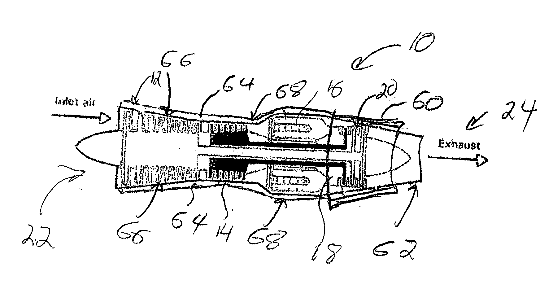
[0026] A retractable afterburner shroud is disclosed. FIG. 5 is a simplified schematic drawing of the turbojet engine 10 with a retractable afterburner shroud 60 in a retracted position in the preferred embodiment of the present invention. The afterburner shroud circumferentially covers an outer surface of the turbojet engine. The afterburner shroud, in the retracted position rests against a back portion of the turbojet engine. Preferably, in the retracted position, the afterburner shroud does not extend beyond the end of the exhaust portion 62 of the turbojet. The afterburner shroud, in the retracted position, conforms to the turbojet engine, thereby reducing total drag by the turbojet engine.

[0027] Addition, the turbojet engine 10 preferably includes a storage tank 64 conforming to most or the entire outer surface of the turbojet engine. The storage tank may be used to hold liquid oxygen for use with the afterburner shroud 60. The storage tank is preferably constructed from the o...


PUM


Abstract

The present invention is a retractable afterburner shroud for use upon a jet engine. The retractable shroud conforms to an outer surface of a jet engine. The afterburner shroud is affixed by a plurality of moveable support arms. The afterburner shroud is retractable. During operation of the afterburner shroud, the afterburner shroud is extended rearward toward the exhaust of the jet engine. A storage tank provides liquid oxygen through the support arms to a mixing ring located within the afterburner shroud. The mixing ring mixes the liquid oxygen and fuel to form a combustible mixture. The combustible mixture is injected into the exhaust wherein the mixture is ignited. The ignited mixture provides additional thrust for the jet engine.

Description

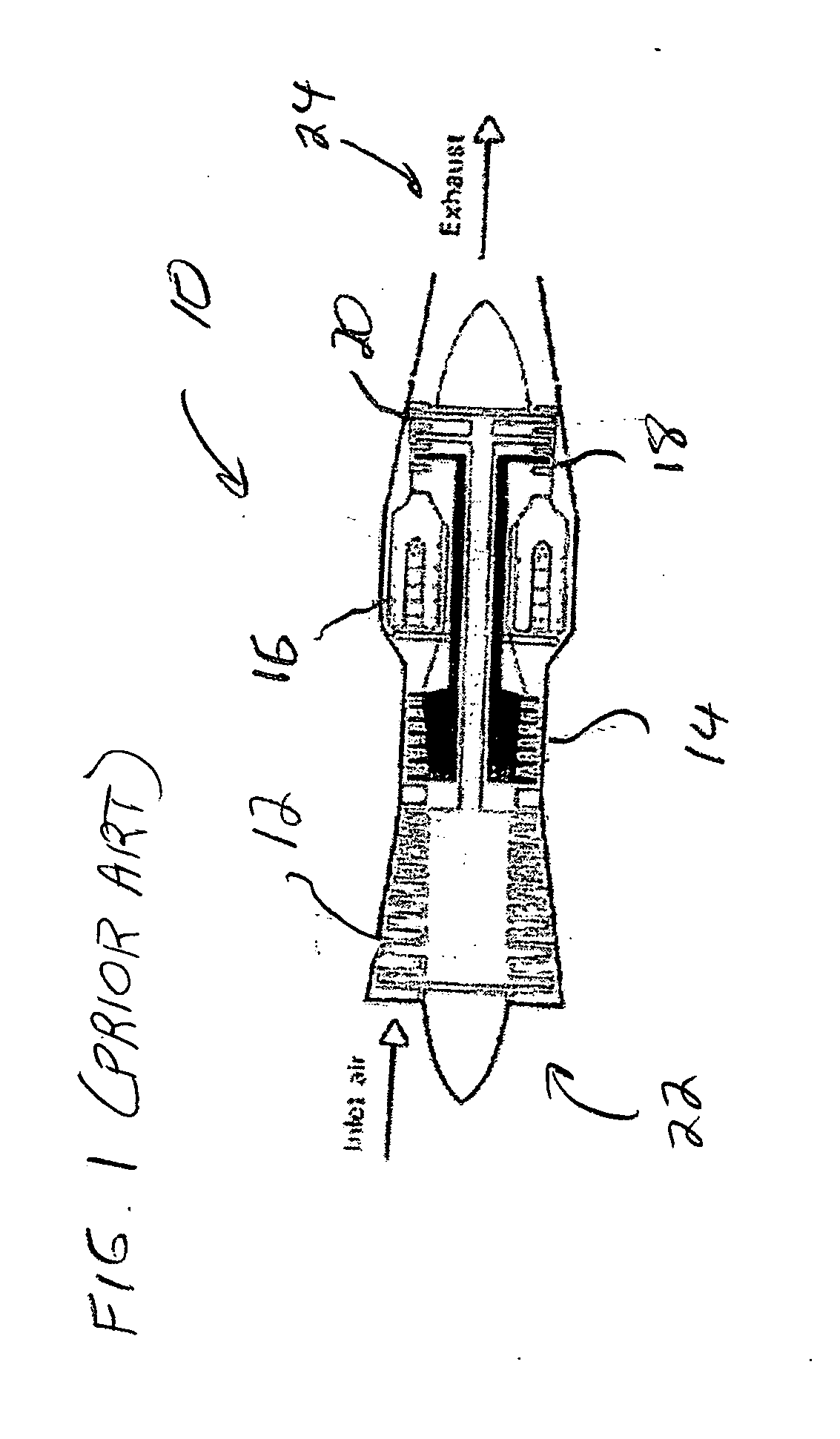
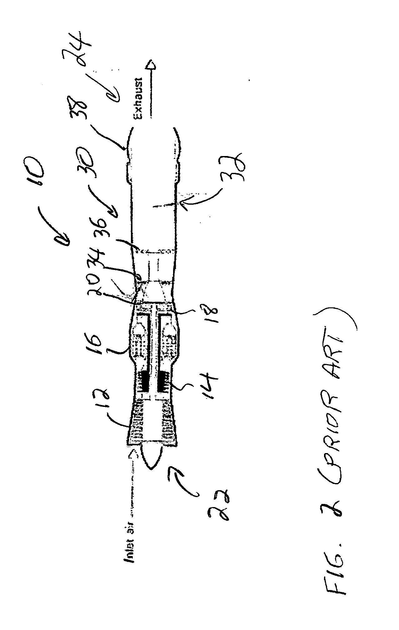
BACKGROUND OF THE INVENTION [0001] 1. Field of the Invention [0002] This invention relates to propulsion systems. Specifically, the present invention relates to an afterburner for use on a jet engine. [0003] 2. Description of the Related Art [0004] Tremendous advances have been made within the first century of aviation. One of the most important advances is the jet engine. Currently, jet engines fall into two broad categories, turbojet and turbofan systems. FIG. 1 illustrates a simplified schematic drawing of a conventional turbojet engine 10. The turbojet engine includes a low pressure compressor 12, a high pressure compressor 14, a combustor 16, a high pressure turbine 18, and a low pressure turbine 20. In the turbojet engine, air comes through an inlet 22 and passes through each component of the engine. The compressor raises the pressure of the inlet air. The pressure ratio varies for different engines, but may approach 30 to 1. The high pressure air enters the combustor where fu...

Claims


Application Information

Patent Timeline
IPC IPC(8): F02K3/10
CPCF02K3/10
Inventor DUNBAR, DONAL S. JR.
Owner ADTECH
Why Eureka
Try Eureka