
Vortex tube cooling system

a cooling system and vortex tube technology, applied in refrigeration machines, surveying, borehole/well accessories, etc., can solve problems such as system impracticality for many subsurface operations, and achieve the effect of reducing fluid pressur

Inactive Publication Date: 2005-11-24
SCHLUMBERGER TECH CORP
View PDF19 Cites 43 Cited by
  • Summary
  • Abstract
  • Description
  • Claims
  • Application Information

AI Technical Summary

Benefits of technology

[0011] The invention provides a vortex tube cooling system. The system includes a housing adapted for subsurface disposal, the housing containing: a first pressure chamber adapted to sustain high fluid pressure; a vortex tube coupled to the first pressure chamber; a cooling chamber coupled to the vortex tube; a second

Problems solved by technology

A drawback of the system proposed in the '957 patent is the need for a pressurized gas source at the surface for continuous gas feed, making the system impractical for many subsurface operations.

Method used


Image

  • Vortex tube cooling system
  • Vortex tube cooling system
  • Vortex tube cooling system

Examples


Embodiment Construction

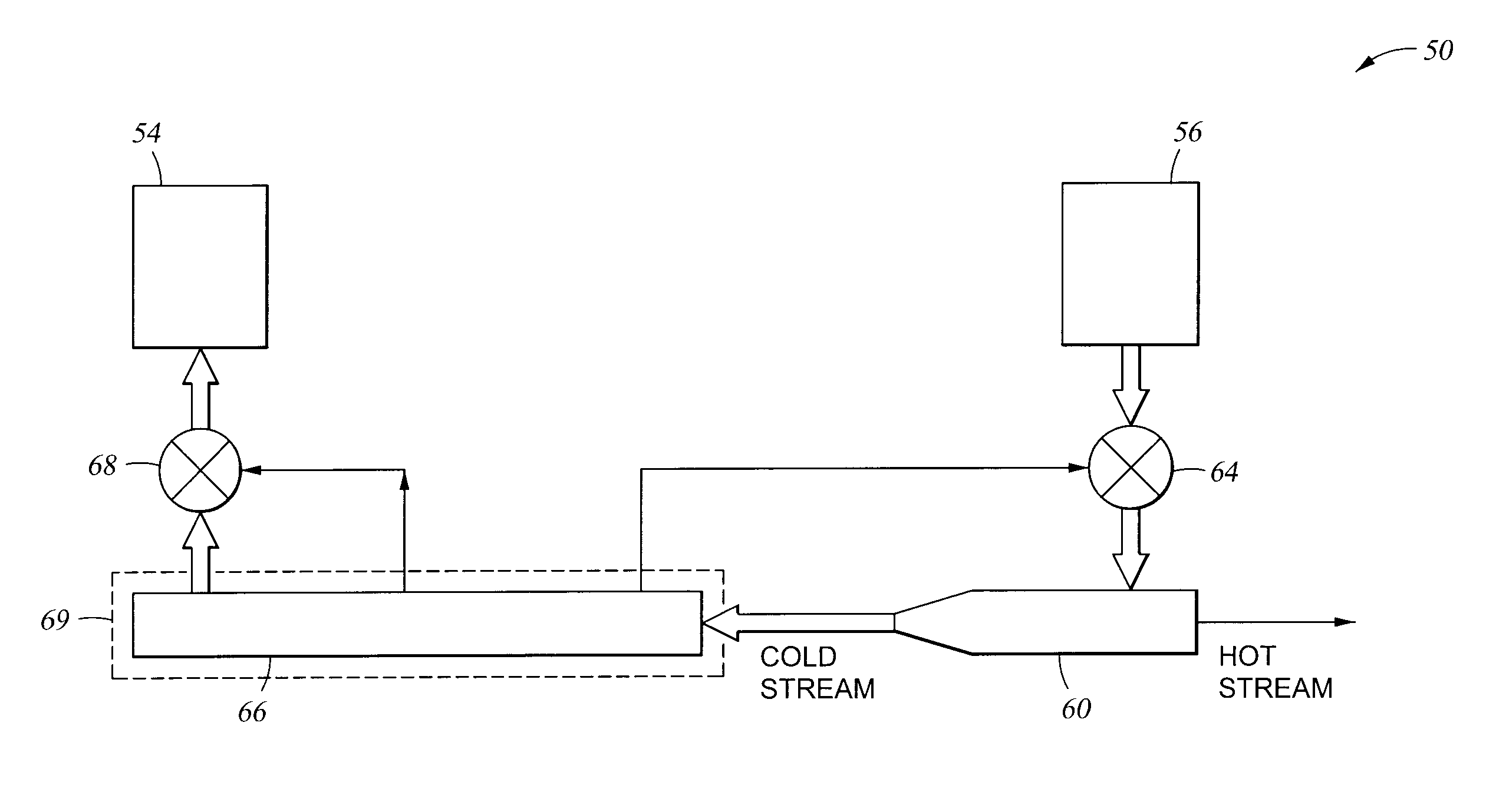
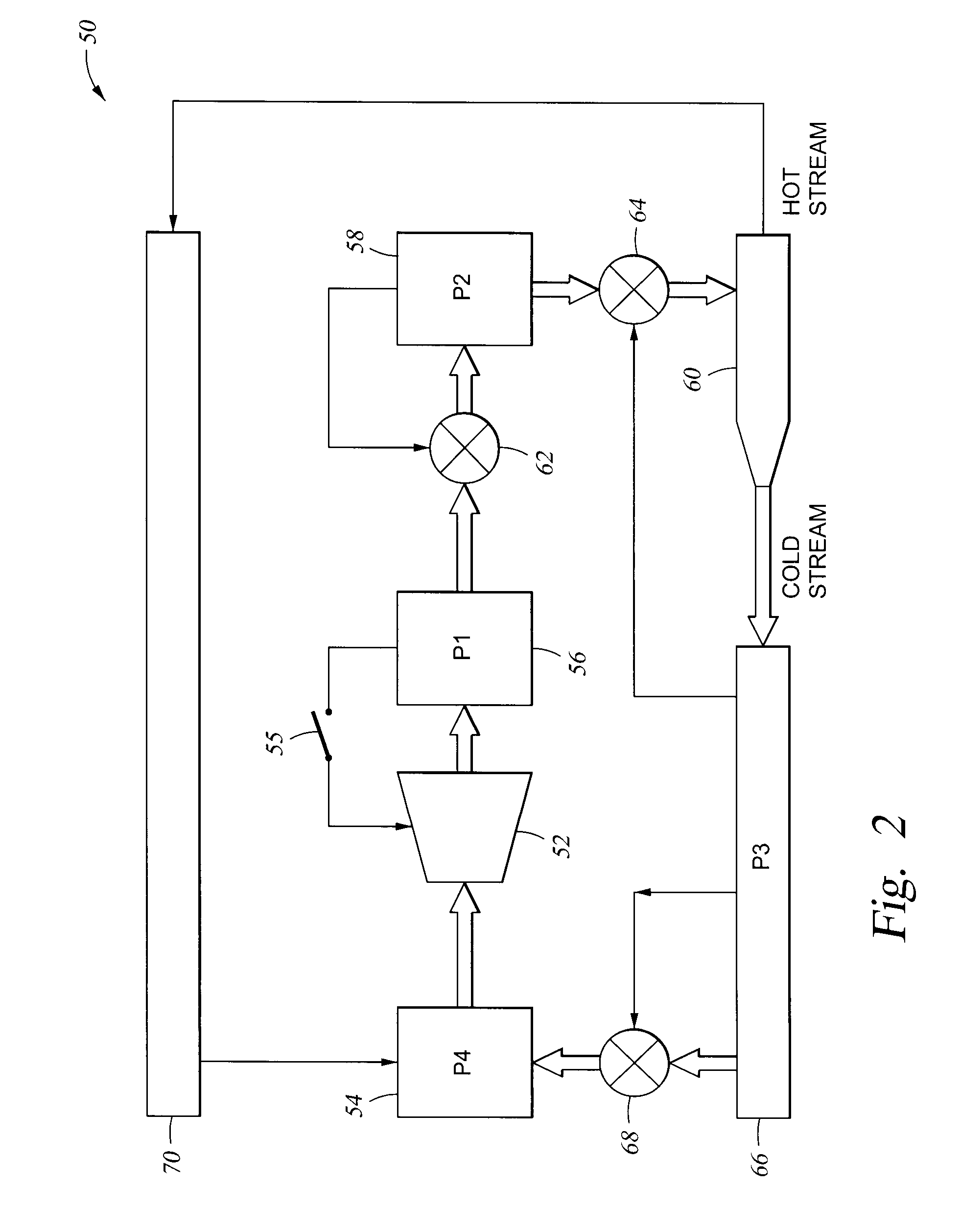
[0020] The disclosed cooling systems are based on a vortex tube to provide cooling. These cooling techniques are not limited to any particular field, they apply to any application where cooling is desired.

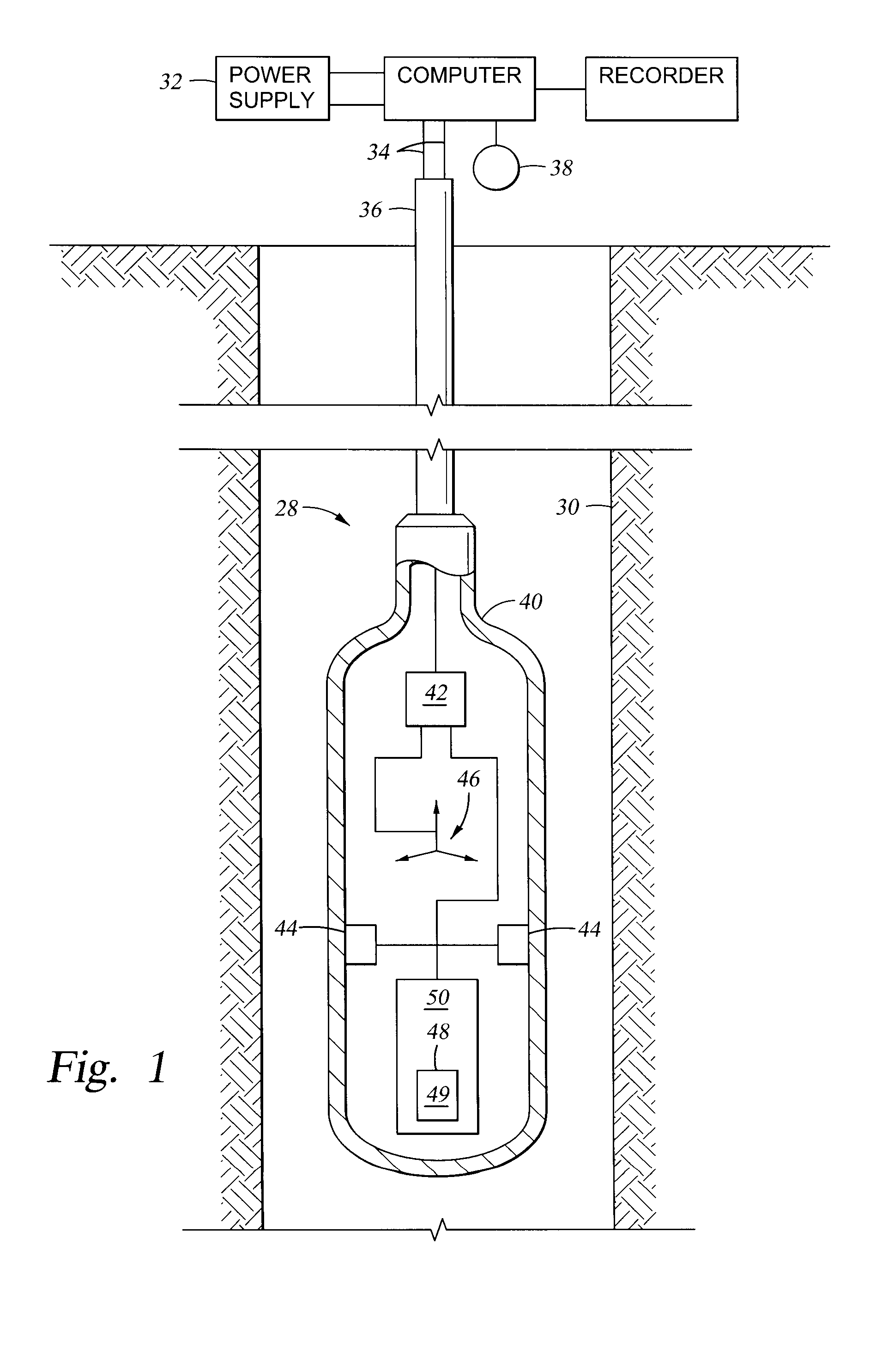
[0021]FIG. 1 shows an instrument designed for subsurface logging operations including a vortex tube cooling system 50 of the invention. The downhole tool 28 is disposed in a borehole 30 that penetrates an earth formation. The cooling system 50 includes a cooling chamber 48 adapted to house the component(s) 49 (e.g. electronics) to be cooled. The tool 28 also includes a multi-axial electromagnetic antenna 46, a conventional source / sensor 44 array for subsurface measurements (e.g., nuclear, acoustic, gravity), and an circuit junction 42. The tool housing 40 may be any type of conventional shell, such as a metallic, non-metallic, or composite sleeve as known in the art. The tool 28 is shown supported in the borehole 30 by a multi-wire cable 36 in the case of a wireline system or a dr...


PUM


Abstract

Systems and methods for cooling a component within a housing adapted for subsurface disposal using a vortex tube. The housing contains a first pressure chamber; a vortex tube coupled to the first pressure chamber; a cooling chamber coupled to the vortex tube; and a second pressure chambercoupled to the cooling chamber; wherein the pressure chambers are adapted to stimulate a cool fluid flow from the vortex tube into the cooling chamber. A cooling method entails disposing the component to be cooled within the cooling chamber and adapting the system pressure chambers to stimulate a cool fluid flow from a vortex tube into the cooling chamber.

Description

BACKGROUND OF INVENTION [0001] 1. Field of the Invention [0002] The present invention relates generally to cooling systems and techniques using vortex tubes. [0003] 2. Background Art [0004] The use of vortex tubes (also know as the “Ranque Tube”, “Hilsch Tube”, “Ranque-Hilsch Tube”, and “Maxwell's Demon”) to implement systems for emitting colder and hotter gas streams is well known (See U.S. Pat. Nos. 1,952,281, 3,208,229, 4,339,926). A vortex tube offers a simple method of cooling using compressed air. Compressed air at high pressure is passed through a nozzle that sets the air in a vortex motion inside the vortex tube. A valve at one end of the tube allows the warmed air from this first vortex to escape. Some of the air that does not escape heads back up the tube as a second vortex inside the low pressure inner area of the larger first vortex. The inner vortex loses heat and exits through the other end of the tube as a cold air stream. Further description of vortex tubes can be fo...

Claims


Application Information

Patent Timeline
IPC IPC(8): E21B47/01F25B9/02F25B9/04
CPCF25B9/04E21B47/011E21B47/017E21B47/0175
Inventor GUNAWARDANA, RUVINDAARZOUMANIDIS, G. ALEXIS
Owner SCHLUMBERGER TECH CORP
Features
  • Generate Ideas
  • Intellectual Property
  • Life Sciences
  • Materials
  • Tech Scout
  • Unparalleled Data Quality
  • Higher Quality Content
  • 60% Fewer Hallucinations
Learn More