Apparatus and method for controlling heating operation in heat pump system
Inactive Publication Date: 2005-11-24
LG ELECTRONICS INC
View PDF5 Cites 20 Cited by
Summary
Abstract
Description
Claims
Application Information
AI Technical Summary
This helps you quickly interpret patents by identifying the three key elements:
Problems solved by technology
Method used
Benefits of technology
Benefits of technology
[0032] According to the present invention, the tube regions of the outdoor heat exchanger can be switched in turn for a defrosting, such that the heating operation can be continuously performed and the compressor is not required to be stopped or restarted for the defrosting.
Problems solved by technology
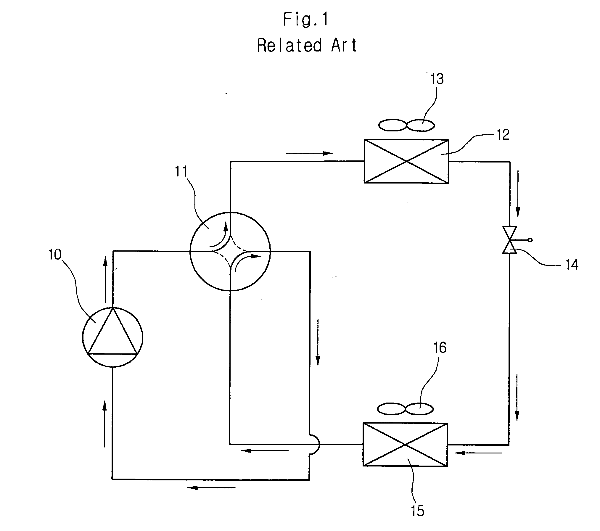
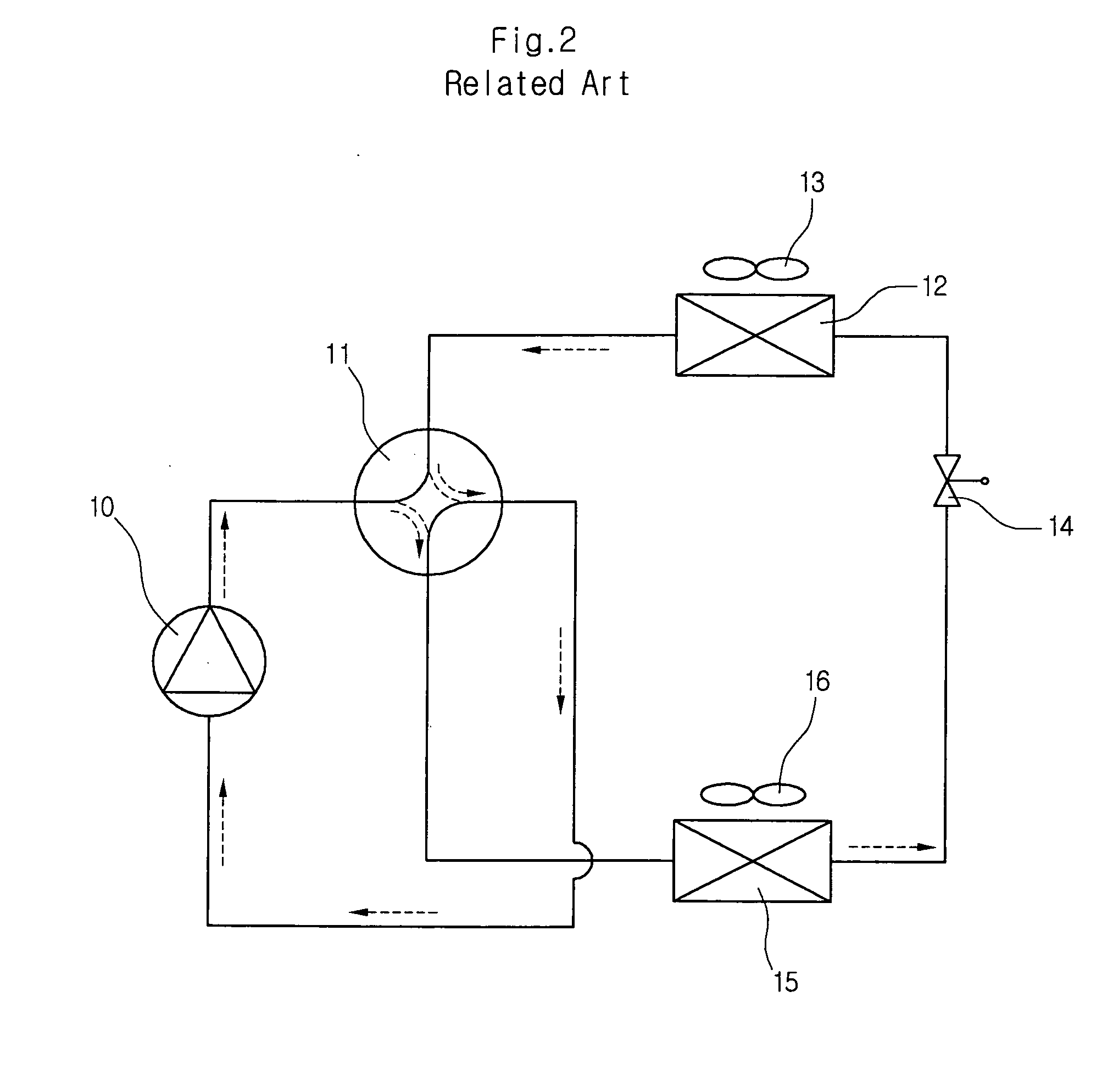
The deposited frost disturbs the heat exchange of the outdoor heat exchanger 12, thereby reducing heat exchange efficiency and increasing heat loss and power consumption as well.
Herein, there occurs a problem in the control of the indoor air, since the heating operation for heating the indoor air is suspended.
Nevertheless, since the heating operation is discretely performed owing to the defrosting operation, the user feels displeasure.
Furthermore, since the heating operation and the defrosting operation are repeated periodically, the compressor 10 also repeats its driving and stopping operations frequently, so that compression loss of the compressor is generated
Method used
Image
Click on the blue label to locate the original text in one second.
Reading with bidirectional positioning of images and text.
Examples
first embodiment
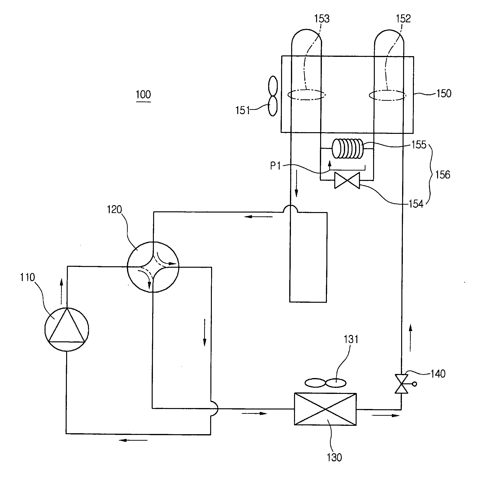
[0049]FIGS. 4 and 5 illustrate a first embodiment of the present invention. In a first embodiment, a tube region of an outdoor heat exchanger is separated into several parts and a partial defrosting operation and partial evaporating operation are performed therein, so that a heating operation is performed continuously.
[0050] An air conditioner 100 is operated in a cooling mode or a heating mode. In the heating mode, the air conditioner 100 performs a heating operation or a defrosting / heating operation, such that the heating operation is not suspended to perform a defrosting operation.
[0051] Referring to FIGS. 4 and 5, the air conditioner 100 includes a compressor 110, a passage switching valve 120, an indoor heat exchanger 130, an expansion unit 140, an outdoor heat exchanger 150, and a defrosting control unit 156.
[0052] Herein, the defrosting control unit 156 is installed inside or outside of the outdoor heat exchanger 150 and it includes a two-way valve 154 for bypassing a refr...
second embodiment
[0076]FIGS. 6 and 7 show a second embodiment of the present invention. In the second embodiment, a defrosting control valve is provided to sequentially perform a defrosting operation and an evaporating operation on a first tube region and a second tube region of an outdoor heat exchanger.
[0077] Referring to FIGS. 6 and 7, an air conditioner 100 is provided with a defrosting control valve 160 for defrosting an entire area of an outdoor heat exchanger 150 while a heating operation is being performed. The defrosting control valve 160 selectively connects an expansion unit 140 with tube regions of the outdoor heat exchanger 150 to determine a region to be defrosted. Here, the defrosting control valve 160 acts as a four-way valve.
[0078] A defrosting operation for a first tube region 152 is shown in FIG. 6. The defrosting control valve 160 connects the expansion unit 140 with the first tube region 152 of the outdoor heat exchanger 150 and also connects a second tube region 153 of the ou...
third embodiment
[0104]FIG. 9 is a structural view of a heat pump system, which uses an LEV for a defrosting control unit according to a third embodiment of the present invention.
[0105] Referring to FIG. 9, an LEV 170 is installed between a first tube region 152 and a second tube region 153 of an outdoor heat exchanger 150. In a heating mode, the LEV 170 is fully opened to pass a refrigerant therethrough. In a defrosting / heating mode, the LEV 170 adjusts its opening to expand and decompress the refrigerant.
[0106] In the defrosting / heating mode, the first tube region 152 is defrosted when the refrigerant flows along the solid line arrows by a switching of a defrosting control valve 160. Herein, the refrigerant flows in sequence through the first tube region 152 for defrosting the first tube region 152, the LEV 170 while expanded and decompressed, and the second tube region 153 to be evaporated.
[0107] The second tube region 152 is defrosted when the refrigerant flows along dashed line arrows by the...
PUM
Abstract
There is provided an air conditioner, and more particularly, an apparatus and method for controlling a heating operation in a heat pumpsystem, in which a continuous heating operation is provided. 1. The apparatus for controlling a heating operation in a heat pumpsystem includes: at least one compressor for compressing a refrigerant into a high-temperature and high-pressure refrigerant vapor; a passage switching unit for switching a refrigerant circulation passage depending on a heating mode or a cooling mode; an indoor heat exchanger for condensing the high-temperature and high-pressure refrigerant vapor for a heating operation or a defrosting / heating operation of the heating mode; an expansion unit through which the condensed refrigerant passes during the defrosting / heating operation; an outdoor heat exchanger for defrosting at least one tube region by using the condensed refrigerant discharged from the expansion unit; and a defrosting control unit for expanding and decompressing the refrigerant that flows between the tube regions, or for bypassing the refrigerant.
Description
BACKGROUND OF THE INVENTION [0001] 1. Field of the Invention [0002] The present invention relates to an air conditioner, and more particularly, to an apparatus and method for controlling a heating operation in a heat pumpsystem, in which a continuous heating operation is provided. [0003] 2. Description of the Related Art [0004] Generally, air conditioners are equipments to circulate a refrigerant through a reiteration of compression, condensation, expansion and evaporation. A combined cooling and heating air conditioner is recently developed. The combined cooling and heating air conditioner includes at least one outdoor unit and at least one indoor unit connected each other and uses a heat pump system that can selectively performs cooling and heating operations. In the air conditioner, at least one indoor unit is disposed at every installation space and a temperature of air is individually controlled at every installation space. [0005] In the combined heating and cooling air condit...
Claims
Application Information
Patent Timeline
Application Date:The date an application was filed.
Publication Date:The date a patent or application was officially published.
First Publication Date:The earliest publication date of a patent with the same application number.
Issue Date:Publication date of the patent grant document.
PCT Entry Date:The Entry date of PCT National Phase.
Estimated Expiry Date:The statutory expiry date of a patent right according to the Patent Law, and it is the longest term of protection that the patent right can achieve without the termination of the patent right due to other reasons(Term extension factor has been taken into account ).
Invalid Date:Actual expiry date is based on effective date or publication date of legal transaction data of invalid patent.

