Switchgear assembly for distribution of electrical power

Inactive Publication Date: 2005-11-24
ABB RES LTD
View PDF7 Cites 2 Cited by
  • Summary
  • Abstract
  • Description
  • Claims
  • Application Information

AI Technical Summary

Benefits of technology

[0005] In the switchgear assembly according to the invention, the commutation switching elements carry the rated current. The disconnection elements which are used for interruption of fault currents therefore do not have to carry the rated current. This makes it possible to use a device whose cost is less than that of a circuit breaker as the disconnection element. Apart

Problems solved by technology

Each of these circuit breakers is designed not only for current interruption but also for carrying the rated current, which makes it necessary for the contact system to have a correspondingly complex configur

Method used


Image

  • Switchgear assembly for distribution of electrical power
  • Switchgear assembly for distribution of electrical power
  • Switchgear assembly for distribution of electrical power

Examples


first embodiment

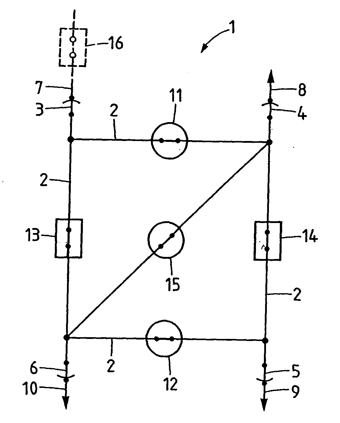
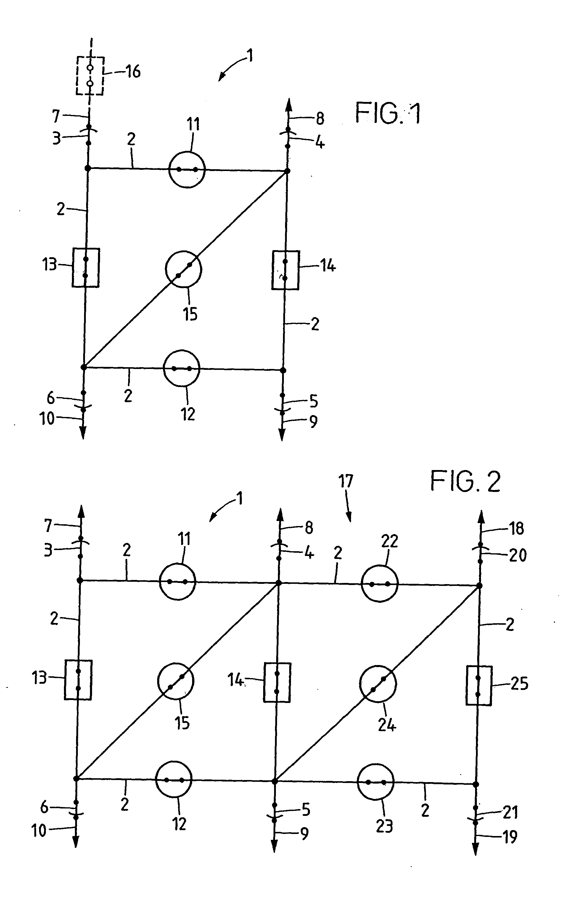
[0017]FIG. 1 shows the basic unit 1 of a switchgear assembly according to the invention, which has a ring busbar 2, four outgoers 7, 8, 9, 10 which are connected via a respective isolator 3, 4, 5 and 6 to the busbar 2, as well as two commutation switching elements 11, 12 and two disconnection elements 13, 14, which are arranged in the busbar 2 and are closed during normal operation. The commutation switching element 11 connects the outgoers 7 and 8, which are themselves connected to the outgoers 10 and 9, respectively, via the respective disconnection elements 13 and 14. The commutation switching element 12 connects the outgoers 9 and 10 to one another. Each outgoer 7, 8, 9, 10 is thus connected via a commutation switching element 11 or 12 to one of the adjacent outgoers, and via a disconnection element 13 or 14 to the other of the adjacent outgoers. The basic unit 1 also has a third commutation switching element 15, which is closed during normal operation and is connected in series...

second embodiment

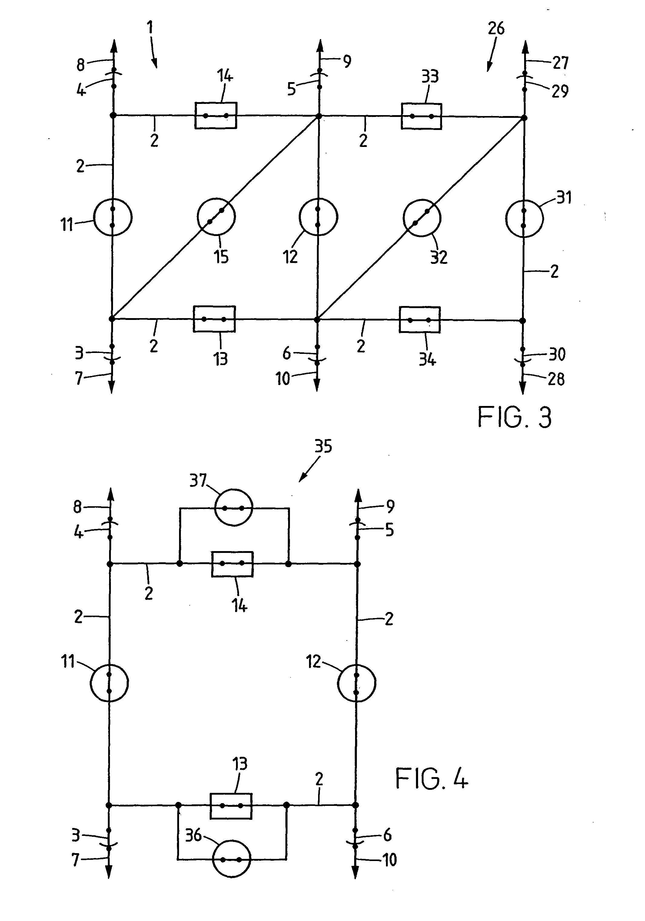
[0032]FIG. 4 shows the basic unit 35 for a switchgear assembly according to the invention. This basic unit 35 is partially constructed in the same way as the basic unit 1 shown in FIG. 1. Components which correspond to one another are therefore annotated by the same reference symbols in FIGS. 1 and 4. The basic unit 35 likewise has a ring busbar 2, four outgoers 7, 8, 9, 10 which are connected via a respective isolator 3, 4, 5 or 6 to the busbar 2, as well as two commutation switching elements 11, 12 and two disconnection elements 13, 14, which are arranged in the busbar 2 and are closed during normal operation. The commutation switching element 11 connects the outgoers 7 and 8, which are themselves connected to the outgoers 10 and 9, respectively, via the respective disconnection elements 13 and 14. The commutation switching element 12 connects the outgoers 9 and 10 to one another. Each outgoer 7, 8, 9, 10 is thus connected via a commutation switching element 11 or 12 to one of the...


PUM


Abstract

The basic unit (1) of a switchgear assembly has a ring busbar (2), four outgoers (7, 8, 9, 10) which are connected to the busbar (2) via a respective isolator (3, 4, 5, 6), as well as two commutation switching elements (11, 12) and two disconnection elements (13, 14), which are arranged in the busbar (2) and are closed during normal operation. Each outgoer (7, 8, 9, 10) is connected via a commutation switching element (11, 12) to one of the adjacent outgoers, and via a disconnection element (13, 14) to the other of the adjacent outgoers. The basic unit (1) also has a third commutation switching element (15), which is closed during normal operation and is connected in series both with the first commutation switching element (11) and with the second commutation switching element (12). Each disconnection element (13, 14) is thus bridged by a parallel current path comprising two commutation switching elements (11, 15; 12, 15) which are in each case connected in series. The commutation switching elements (11, 12, 15) are designed for carrying the rated current and, briefly, a fault current, but are not designed for disconnection of fault currents. In contrast, the disconnection elements (13, 14) are designed for fault current interruption, but not for carrying the rated current.

Description

FIELD OF THE INVENTION [0001] The invention relates to a switchgear assembly for distribution of electrical power, as claimed in the precharacterizing clause of claim 1, and to a method for operation of this switchgear assembly. BACKGROUND OF THE INVENTION [0002] In conventional switchgear assemblies having a ring busbar and having a number of outgoers, circuit breakers which are closed during normal operation are arranged in the busbar, between each two adjacent outgoers. Each of these circuit breakers is designed not only for current interruption but also for carrying the rated current, which makes it necessary for the contact system to have a correspondingly complex configuration. The circuit breakers (one for each outgoer) are, however, operated very rarely, and generally only in the event of a fault, but make up a high proportion of the costs of the overall switchgear assembly. SUMMARY OF THE INVENTION [0003] The present invention is based on the object of providing a switchgea...

Claims


Application Information

Patent Timeline
IPC IPC(8): H02H7/28H02J3/00
CPCH02J3/00H02H7/28
Inventor NIEMEYER, LUTZ
Owner ABB RES LTD
Why Eureka
Try Eureka