Prefabricated stand for hydronic systems

a technology for hydronic systems and stands, applied in the direction of fluid heaters, heating types, lighting and heating apparatus, etc., can solve the problems of high installation cost of hydronic systems, time and effort required, complex and expensive,

Inactive Publication Date: 2005-11-24
SIMENSEN THOMAS O +1
View PDF15 Cites 14 Cited by
  • Summary
  • Abstract
  • Description
  • Claims
  • Application Information

AI Technical Summary

Problems solved by technology

Unfortunately, those advantages are offset, at least in part, by the relatively high installation costs of hydronic systems.
The time and effort required add substantial

Method used


Image

  • Prefabricated stand for hydronic systems
  • Prefabricated stand for hydronic systems
  • Prefabricated stand for hydronic systems

Examples


Embodiment Construction

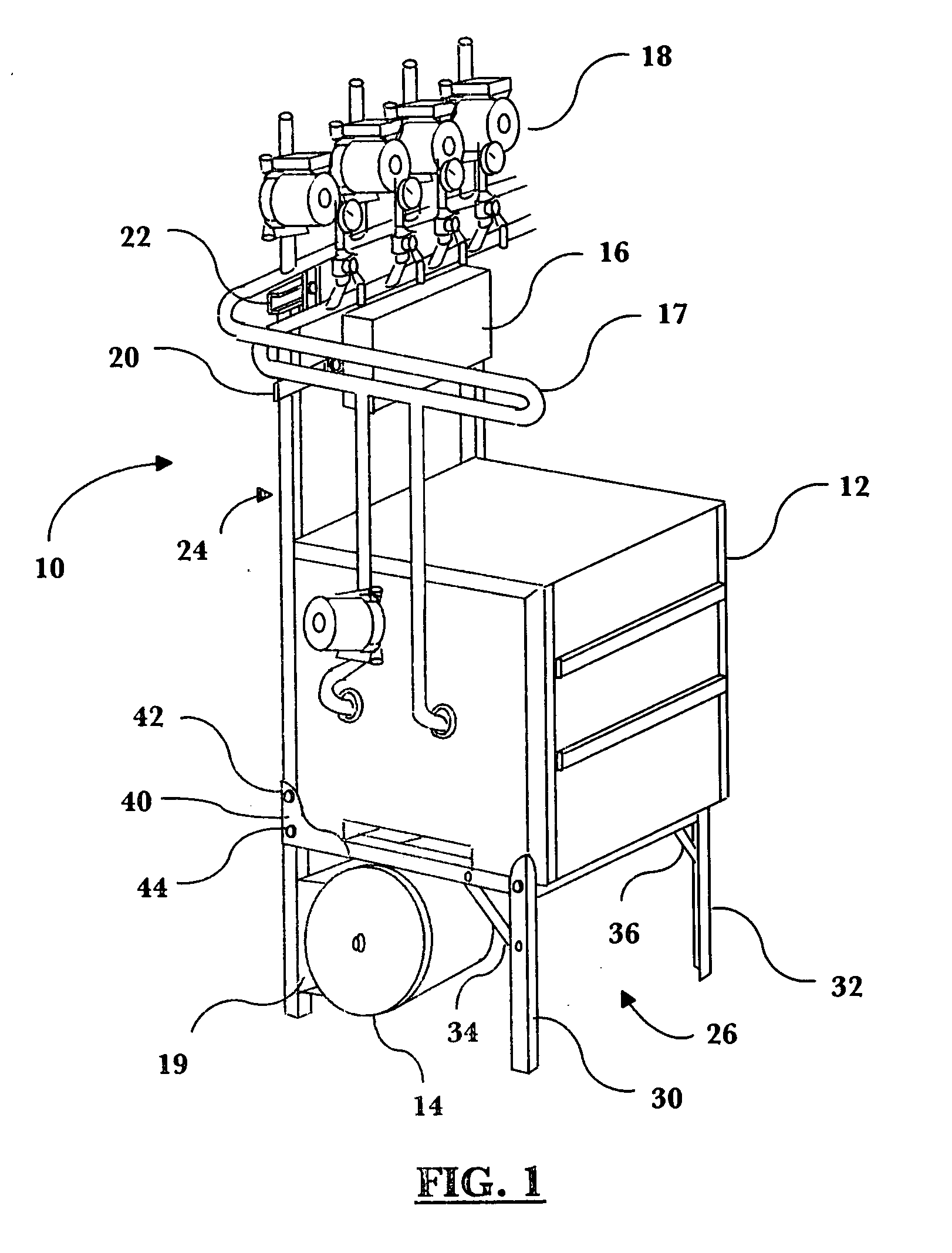
[0015]FIG. 1 illustrates a stand assembly 10 incorporating the principles of the present invention. The stand assembly 10 supports a variety of hydronic system components, including a boiler 12, an expansion tank 14, an electronic control panel 16, a primary loop module 17, and a zone manifold module 18. The expansion tank 14 is secured to the stand assembly 10 via a tank mounting bracket 19. The electronic control panel 16 is secured to the stand assembly 10 via an electronics mounting bracket 20. The zone manifold module 18 can secured to the stand assembly 10 via a conventional manifold mounting mechanism such as a uni-strut 22, or as described with reference to a specific zone manifold module.

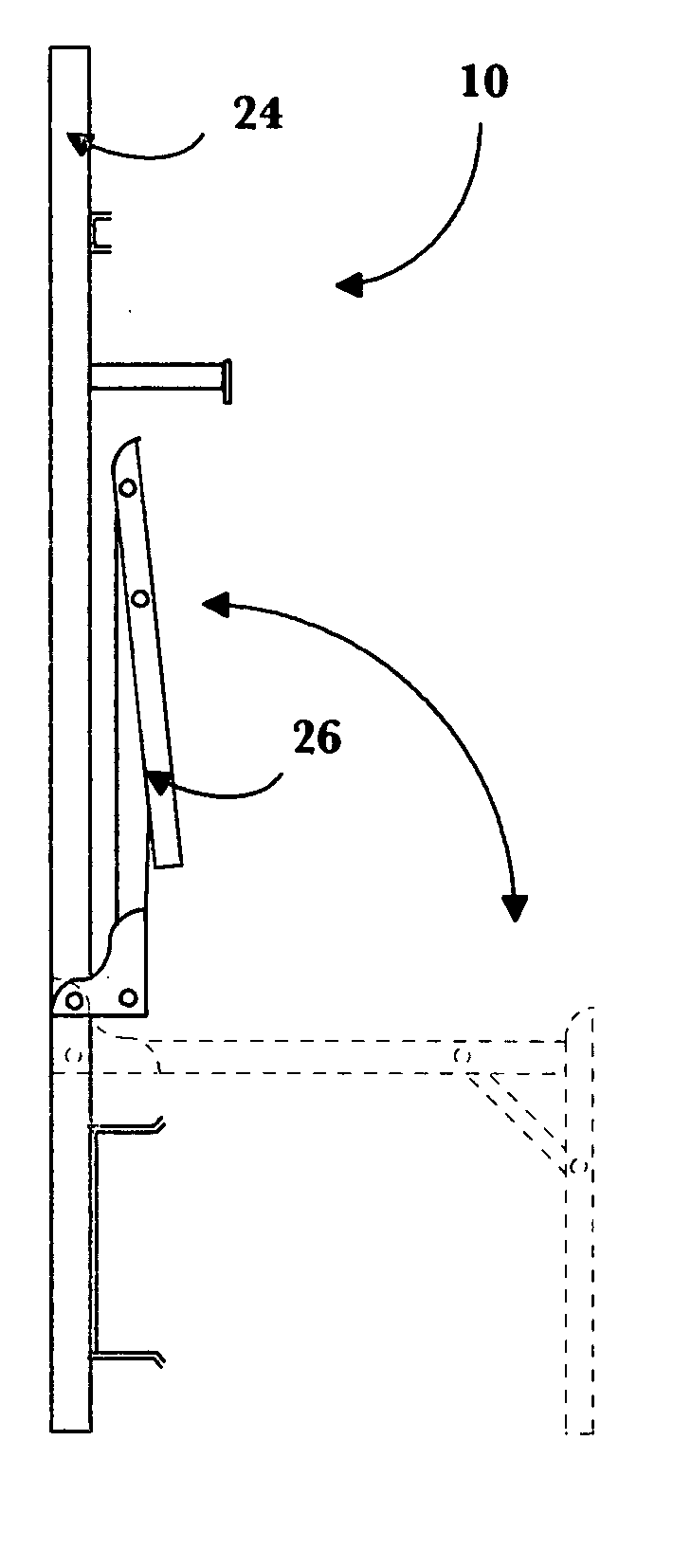
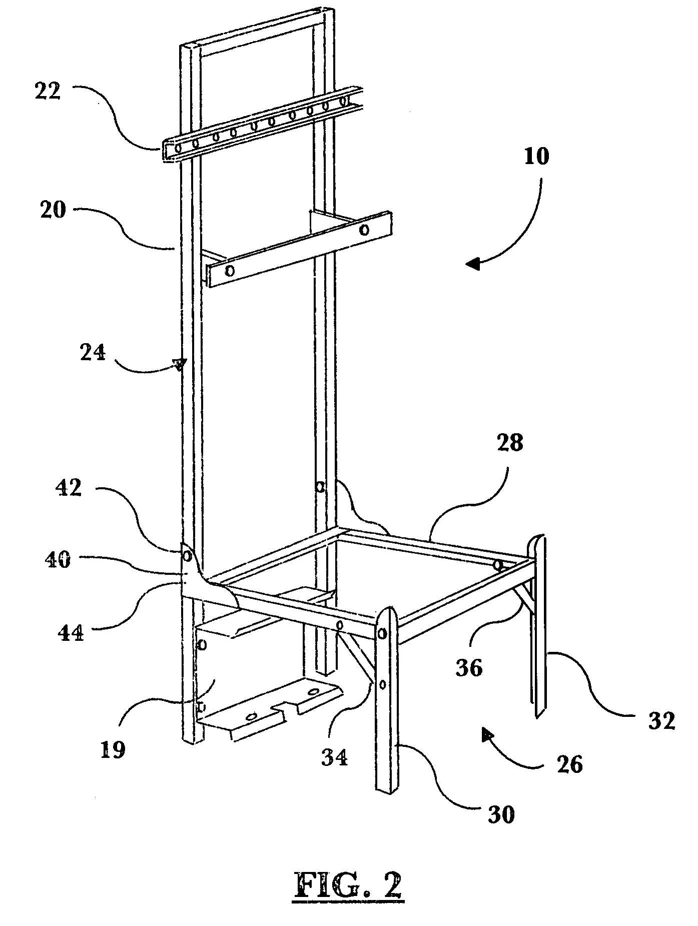
[0016] Details of the stand assembly 10 are shown in FIGS. 2 through 4. The stand assembly 10 includes a fixed back portion 24. A selectively movable platform portion 26 is connected to the back portion 24.

[0017] The platform portion 26 includes a platform 28 adapted and constructed to su...


PUM


Abstract

A stand assembly for hydronic circulation systems includes a fixed back portion. A selectively movable platform portion is connected to the back portion. The stand assembly is selectively movable between a folded shipping position and an unfolded installation position by selectively moving the platform portion.

Description

FIELD OF THE INVENTION [0001] The invention relates generally to components for hydronic systems. Specifically, the invention relates to stands for supporting hydronic heating system components. BACKGROUND OF THE INVENTION [0002] The advantages of hydronic heating systems are well-known. Hydronic systems offer levels of comfort, efficiency, and quiet operation that are seldom obtained by forced-air arrangements. Unfortunately, those advantages are offset, at least in part, by the relatively high installation costs of hydronic systems. Hydronic systems typically include a boiler supplying heat exchange medium to in-floor or baseboard heat exchangers. Conduits, pumps, and valves are connected to circulate the heat exchange medium between the boiler and the heat exchangers. Customarily, the conduits, pumps, and valves are collected and assembled on-site. Many applications require on-site fabrication of a boiler stand as well (for example, when system components are located in a garage)...

Claims


Application Information

Patent Timeline
IPC IPC(8): F24D3/00F24D19/00F24H9/06
CPCF24D19/00Y10T29/53F24D19/0097F24H9/06
Inventor SIMENSEN, THOMAS O.SIMENSEN, TORBJORN O.
Owner SIMENSEN THOMAS O
Why Eureka
Try Eureka