Cycling water area energy balance control box

A regional energy and balance control technology, applied in the field of water circulation, can solve problems such as fire, equipment burning components, easy-to-invade equipment main body, etc., and achieve the effect of reducing the risk of intrusion and damage

Pending Publication Date: 2018-09-28
江含飞
View PDF0 Cites 1 Cited by
  • Summary
  • Abstract
  • Description
  • Claims
  • Application Information

AI Technical Summary

Problems solved by technology

[0003] The existing energy balance control box in the circulating water area is located in a water-rich area, and most of it is directly exposed to the outside air. ...

Method used


Image

  • Cycling water area energy balance control box
  • Cycling water area energy balance control box
  • Cycling water area energy balance control box

Examples


Embodiment 1

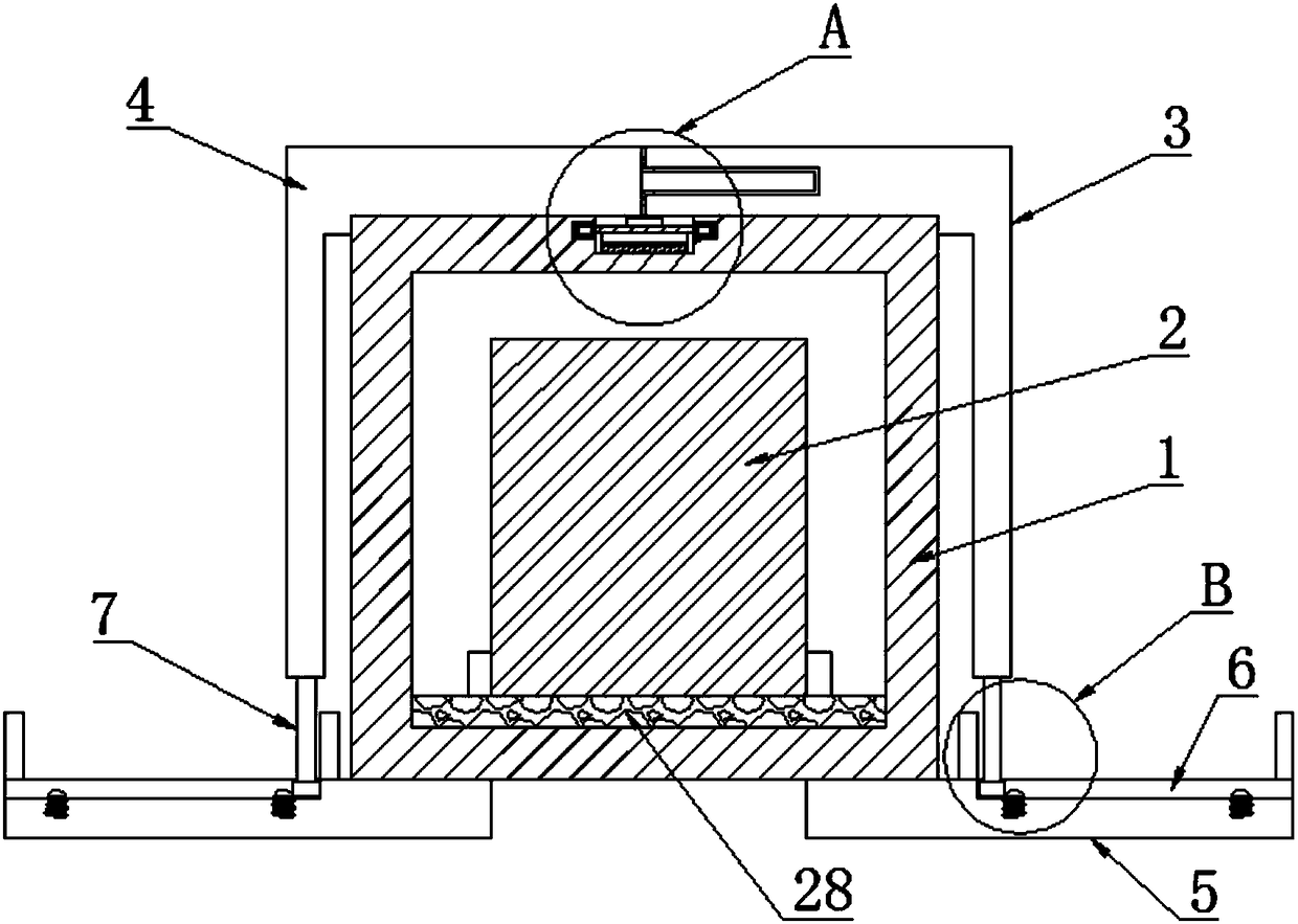
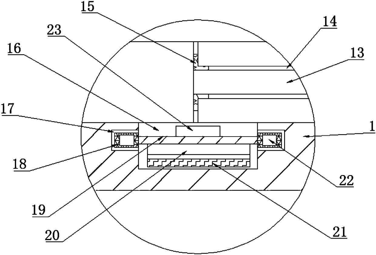
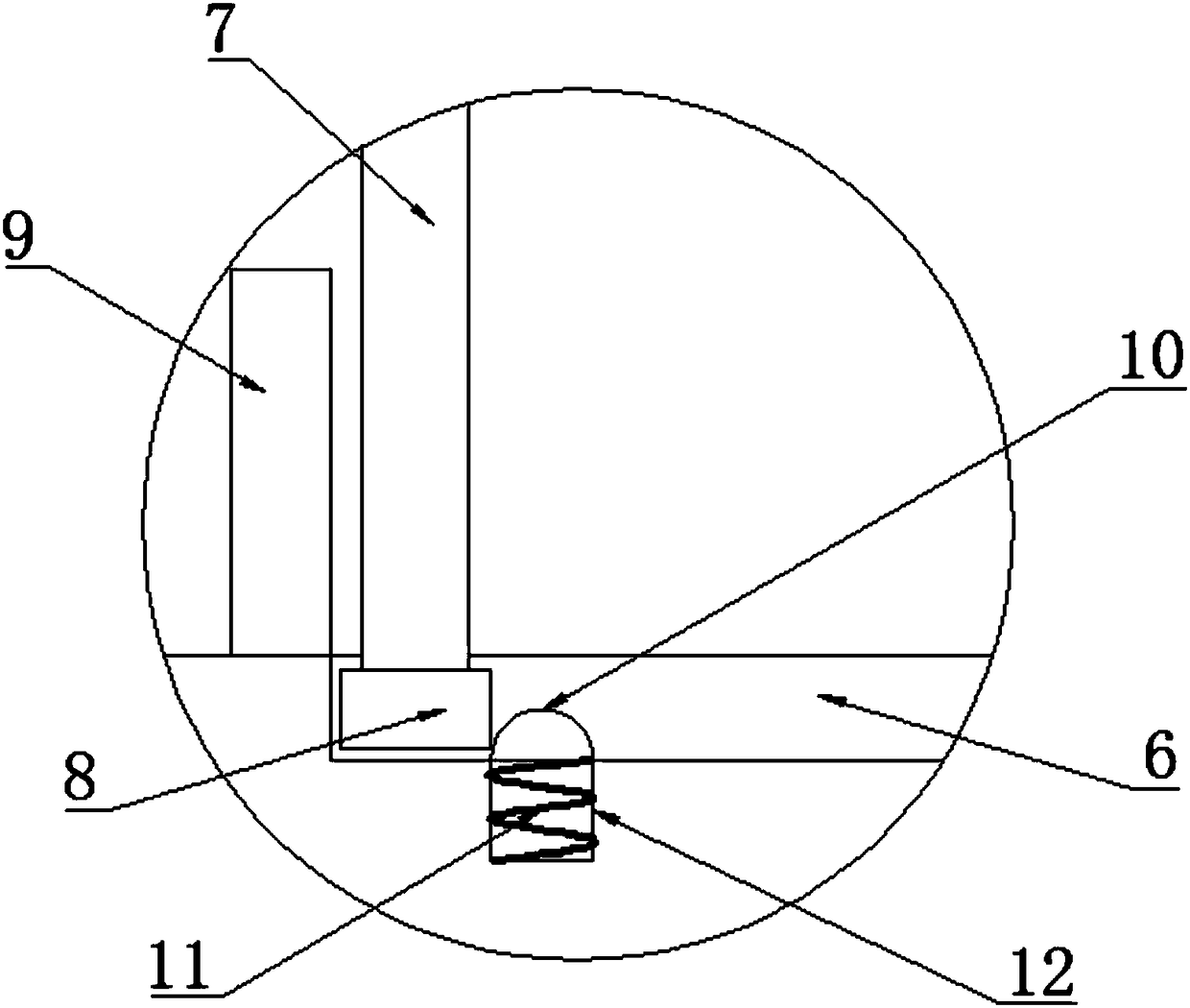
[0022] Such as Figure 1-7 As shown, a circulating water area energy balance control box of the present invention includes a box body 1, a device main body 2 is placed in the box body 1, four installation bases 5 are fixedly connected to the lower end of the box body 1, and the upper end of the installation base 5 is provided with The first chute 6, the upper end of the box body 1 is respectively provided with a left waterproof cover 4 and a right waterproof cover 3 from left to right, the upper end of the box body 1 is provided with two T-shaped chutes 25 from left to right, and the left waterproof cover 4 The T-shaped slide block 24 that matches with T-shaped chute 25 is fixedly connected with the lower end of the right waterproof cover 3, and the position corresponding to the first chute 6 at the lower end of the left waterproof cover 4 and the right waterproof cover 3 is fixedly connected with a moving bar 7. The lower end of the rod 7 is fixedly connected with a first sli...


PUM


Abstract

The invention discloses a cycling water area energy balance control box, and belongs to the technical field of water circulation. The cycling water area energy balance control box comprises a box bodyin which an equipment body is placed, four installation pedestals are fixedly connected with the lower end of the box body, a first sliding chute is formed in the upper end of each installation pedestal, a left waterproof cover and a right waterproof cover are separately arranged at the upper end of the box body from left to right, two T-shaped sliding chutes from left to right are formed in theupper end of the box body, T-shaped sliding blocks matched with the T-shaped sliding chutes are fixedly connected with the lower ends of the left waterproof cover and the right waterproof cover, moving rods are fixedly connected with the positions, corresponding to the first sliding chutes, on the lower ends of the left waterproof cover and the right waterproof cover, a first sliding block is fixedly connected with the lower end of each moving rod, a clamping plate is fixedly connected with the right end of the left waterproof cover, a clamping groove matched with the clamping plate is formedin the left end of the right waterproof cover, and a groove in the front and back direction are formed in the middle position of the upper end of the box body. According to the cycling water area energy balance control box provided by the invention, the invasion of external water can be reduced, and the damage risk of the internal equipment can be reduced.

Description

technical field [0001] The invention relates to the technical field of water circulation, and more specifically relates to an energy balance control box for a circulating water area. Background technique [0002] Circulating water is composed of circulating pump, control system, one-way valve, etc. It forms a complete hot water circulating system with water heater, hot water main pipe and hot water return pipe. The working principle is that the control system sends a signal to the circulating pump, and the circulating pump drives The water circulates inside to start the water heater to heat up, and it stops working when the set time or temperature is reached, and hot water is available immediately when the hot water is used. [0003] The existing energy balance control box in the circulating water area is located in a water-rich area, and most of it is directly exposed to the outside air. Once water enters the control box, it is easy to invade the main body of the equipment,...

Claims


Application Information

Patent Timeline
IPC IPC(8): H05K5/06H05K5/00
CPCH05K5/06H05K5/0004
Inventor 江含飞
Owner 江含飞
Why Eureka
Try Eureka