Hydronic/biphasic radiator with reduced thermal inertia and low environmental impact

a biphasic radiator and thermal inertia reduction technology, applied in the field of radiators, can solve the problems of inability to prescind, poor comfort of users, and the inability to even achieve the surface distribution of temperature on a traditional-type heater, and achieve the effect of facilitating the nucleate boiling process

Active Publication Date: 2017-11-28
I R C A S P A IND RESISTENZE CORAZZATE E AFFINI
View PDF16 Cites 1 Cited by
  • Summary
  • Abstract
  • Description
  • Claims
  • Application Information

AI Technical Summary

Benefits of technology

[0014]Advantageously, the radiating body is made of aluminium and the pipes which are orthogonal to the longitudinal axis of the collector are connected to the collector itself by brazing and / or interlocking systems with suitable gaskets. These pipes, which are vertical in use, are in number and height such as to satisfy the thermal power to be supplied as a function of the maximum dimensions required by the market or allowed by the various regulations and from the viewpoint of reducing the radiator weight. The choice to obtain the vertical pipes by extrusion of aluminium alloys further allows to construct radiators of varying height based also on the specific requirements of the customer without additional investment costs.
[0015]The aluminum alloy used allows the precision mechanical processes which are necessary in order to provide the joints between collector and vertical pipes. The use of aluminium alloy occurs in the most limited quantities possibile, in order to reduce the thermal inertia, the environmental impact and the cost of the device. Aluminium alloy also lends itself to extremely accurate extrusion processes, thus responding to both technological / construction requirements and architectural design requirements.
[0018]The heating intermediate vector fluid in the biphasic state has low environmental impact (low direct greenhouse effect and non-existent potential for stratospheric ozone destruction, i.e. low GWP and zero ODP), and is used in limited quantity, in the initial liquid state, in comparison with the total internal volume of the radiator. Said intermediate vector fluid, initially within the collector, evaporates on contact with the heat exchanger crossed by the thermo-vector fluid and condensing on the walls of the pipe or the vertical pipes, i.e. on the walls of the internal channels of said vertical pipes, releases the latent evaporation heat making the radiator temperature basically even.
[0023]In order to facilitate the nucleate boiling process, allowing the radiator to be used also in the case of the characteristic inlet temperatures of a heat pump or condensation-type boiler, which are much lower than the inlet temperatures (60-75° C.) of a traditional boiler, the radiator can be equipped with a special valve which allows a level of vacuum to be obtained within the collector, where the intermediate vector fluid is contained, such as to always allow the boiling of the fluid, even for much lower inlet water temperatures.
[0024]The valve in question consists of an external body sealingly fixed to the radiator (preferably on the collector) with a standard commercial piston and return spring mechanism screwed therein. By means of quick coupling, the valve allows the necessary vacuum to be easily provided within the radiator and the subsequent step of filling the collector with the intermediate vector fluid.

Problems solved by technology

Furthermore, taking into account the aforementioned residential requirements, the objective of reducing energy consumption can only be pursued by means of an integrated approach to the design of the building-installation system and, in this sense, it is not possible to prescind from the necessity of having a plant terminal which integrates well from an architectural viewpoint in the room to be heated, shifting the attention of the architect, rather than that of the final user, towards a product which is also a furnishing component as well as a plant functional element.
From the perspective of reaching comfort in the rooms, it is desired to favour radiant heat exchange, typical of thermosiphons, as much as possible, with respect to the convective one which is typical, for example, of fan coil units, which, in spite of their low inertia, often give rise to situations perceived as being of poor comfort by the user, due to the movement of air, perceived as dry, in the heating phase.
However, it is known that the surface distribution of the temperature can never be even on a traditional-type heater, given that the variation in water temperature through the radiator between inlet and outlet is typically around 10 degrees.
This situation translates into non-optimal use, from the viewpoint of thermal radiation, of the heat exchange surface, at the expense also of the radiator size.

Method used


Image

  • Hydronic/biphasic radiator with reduced thermal inertia and low environmental impact
  • Hydronic/biphasic radiator with reduced thermal inertia and low environmental impact
  • Hydronic/biphasic radiator with reduced thermal inertia and low environmental impact

Examples


Embodiment Construction

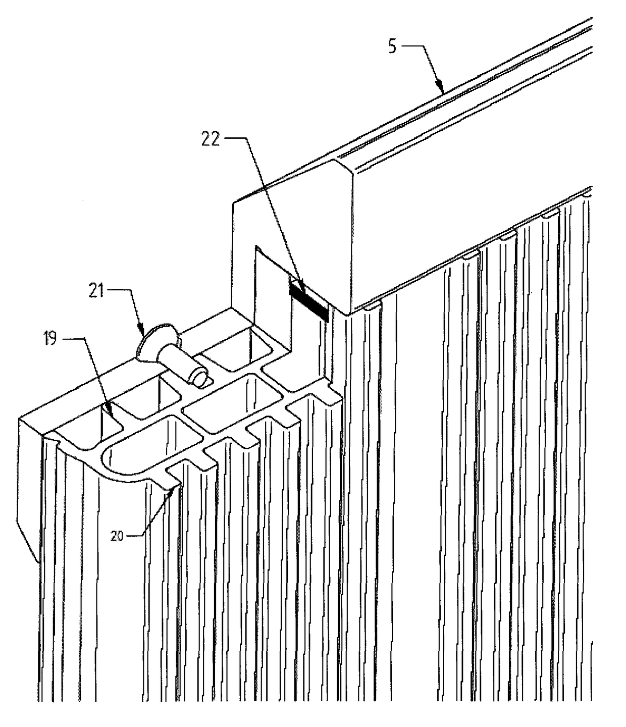
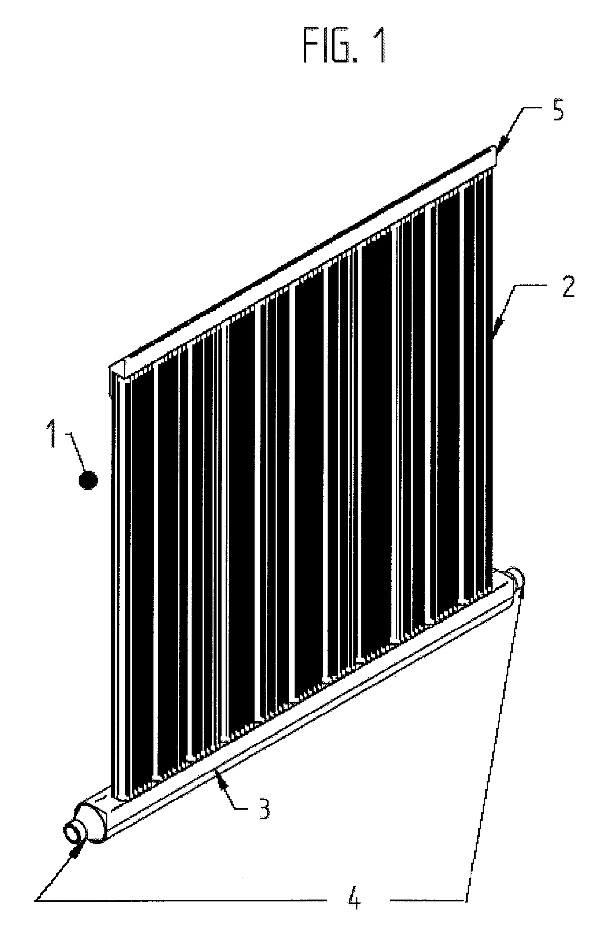
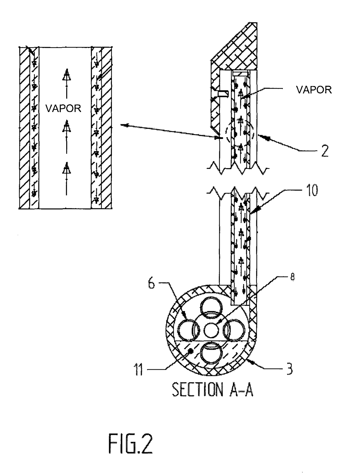
[0041]A hydronic biphasic thermosiphon 1 according to the invention is shown in FIG. 1, where numeral 2 indicates the vertical pipes containing the channels along the walls of which the film of moisture forms during operation, and numeral 3 indicates the collector containing the intermediate vector fluid which, during operation, in contact with heat exchanger 6 which is found within the collector, evaporating, rises up the aforementioned channels before condensing along the walls of the same (FIG. 2).

[0042]The pipe bundle-type heat exchanger, as shown in FIGS. 2 and 3 by a group of four pipes 6, is fixed to collector 3 and terminates with two sealing flanges 16, one at the inlet and the other at the outlet of the thermo-vector fluid, each of which rests on the corresponding abutment of collector 3 and is sealingly welded or brazed 14 onto the latter (FIG. 3). Each flange 16 has one or more holes (FIG. 4) for housing and sealingly fixing the pipes 6 within which the water or another ...


PUM


Abstract

A radiator with reduced thermal inertia, based on the principle of phase changing, using a non-toxic, non-flammable fluid with reduced environmental impact. The radiator is provided by means of vertical pipes which engage a collector containing a pipe bundle-type exchanger with smooth or finned pipes, internally crossed by the thermo-vector fluid of the system, and which heat the intermediate vector fluid, bringing it to the biphasic state. The vector fluid evaporates, rising up the vertical pipes, flowing through the channels obtained in the extruded profiles of the vertical pipes themselves. The fluid re-descends, condensing on the walls, returning into contact with the hot pipes of the exchanger in order to re-evaporate and rise back up the vertical pipes. The film of condensed liquid provides the required heat exchange. The terminal is further equipped with mechanical parts which allow the inserting of temperature sensors for possible monitoring and control of consumption and system operation and control thereof, by means of on-board electronic control devices (electric valves) and remote devices suitably operating in radio-frequency.

Description

CROSS REFERENCE TO RELATED APPLICATIONS[0001]This application is a national phase of PCT application No. PCT / IB 2012 / 054293, filed Aug. 24, 2012, which claims priority to IT patent application No. RM 2011A000449, filed Aug. 25, 2011, all of which are incorporated herein by reference there to.FIELD OF THE INVENTION[0002]The present invention relates to a radiator with low thermal inertia and a very low time constant, operating with thermo-vector fluids such as hot water or glycolate mixtures, operating in biphasic regime, with application in the field of heating systems for residential and commercial buildings.STATE OF THE ART[0003]The current technology most widely diffused in the European field for radiators for domestic or industrial use provides a heat generator (typically a traditional or condensation-type boiler, though, more recently, heat pumps are also increasingly diffused) for single or multi-family use with hydronic distribution of the heat towards radiators, of the therm...

Claims


Application Information

Patent Timeline
Patent Type & Authority Patents(United States)
IPC IPC(8): F28D1/02F28F27/00F24H3/00F28D7/10F24H3/12F28D15/02F28D15/06
CPCF28D1/0226F24H3/004F24H3/12F28D15/02F28F27/00F28D7/103F28D15/06F28D15/0266
Inventor PETERLE, MICHELEVISENTIN, SIMONETRENTIN, DIEGOZOPPAS, FEDERICO
Owner I R C A S P A IND RESISTENZE CORAZZATE E AFFINI
Why Eureka
Try Eureka