Hydronic air heater

a technology of air heater and heater body, applied in the field of hvac systems, can solve problems such as retrofitting or upgrading systems into

Inactive Publication Date: 2017-06-06
MESTEK
View PDF25 Cites 2 Cited by
  • Summary
  • Abstract
  • Description
  • Claims
  • Application Information

AI Technical Summary

Benefits of technology

[0010]It is another object of the present invention to provide a hydronic air heater that can be easily installed on the rooftop of existing buildings.
[0011]It is another object of the present invention to provide a hydronic air heater having increased accuracy and efficiency compared to existing devices.
[0013]It is yet another object of the present invention to provide a hydronic air heater that provides exceptional temperature accuracy and efficiency over widely variable ambient conditions.
[0017]According to yet another embodiment of the present invention, a method of heating a structure is provided. The method includes the steps of providing an enclosure having an air inlet, a closed heating loop including a boiler, a pump and a heating coil with the enclosure, and a blower assembly with the enclosure, controlling the boiler and the pump to provide a heated fluid to the heating coil, controlling the blower assembly to draw air into the enclosure and past the heating coil to warm the air for distribution to the structure, and recovering heat lost from the boiler and the pump and providing the recovered heat to the heating coil.

Problems solved by technology

Often times, however, this is undesirable due to space limitations, complexity of installation and the inability to easily retrofit new or upgraded systems into an existing building.
While certain heating systems can be deployed on the rooftop of buildings (known as packaged rooftop units), thereby providing for ease of installation / retrofitting, hydronic heating systems have typically not been used on the roof because of the need to bring water piping to the roof and concerns about operation at subfreezing temperatures.

Method used


Image

  • Hydronic air heater
  • Hydronic air heater
  • Hydronic air heater

Examples


Embodiment Construction

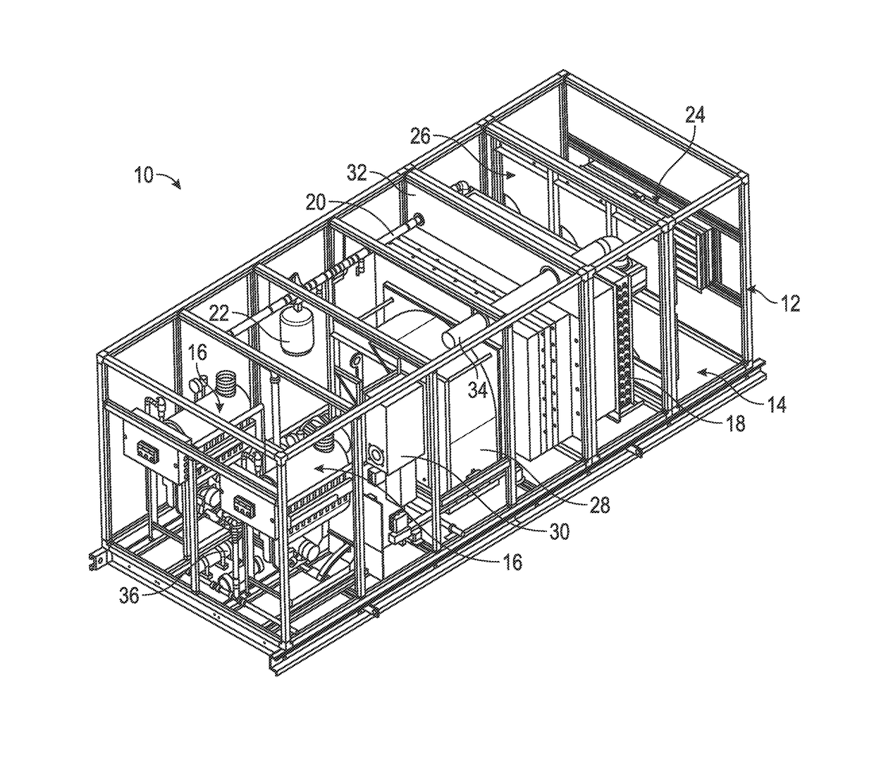
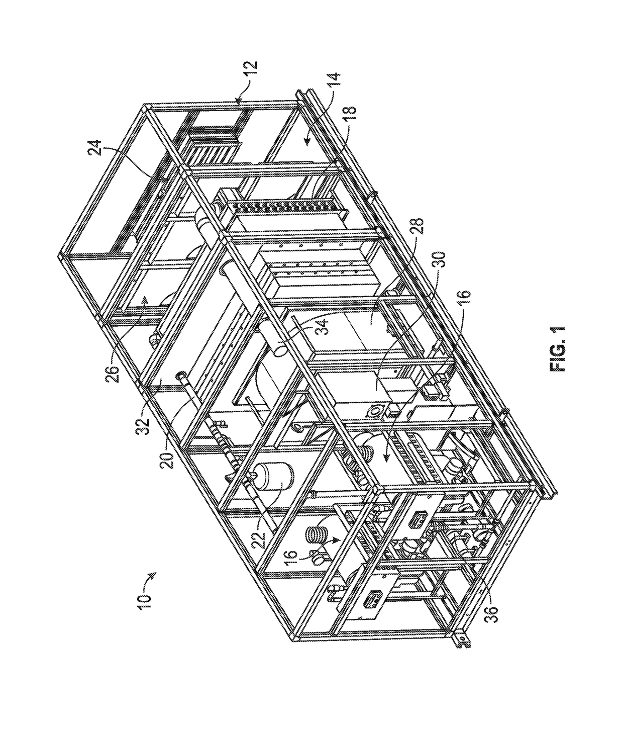
[0022]Referring to FIG. 1, the present invention relates to a packaged hydronic air heater 10. As shown therein, the hydronic air heater includes a frame assembly 12 defining a substantially rectangular enclosure 14 encased by panels (not shown), which hermetically seal the enclosure 14. The hydronic air heater 10 includes one or more boilers 16 disposed within the enclosure 14. In the preferred embodiment, the hydronic air heater 10 has two boilers 16, although more or fewer boilers may be utilized without departing from the broader aspects of the present invention. The boilers 16 are fluidly coupled to a heating coil 18 via pipelines 20, which forms a closed-loop system whereby a fluid is heated by the boilers 16, pumped to the heating coil 18 by a constant speed pump (not shown), and eventually returned to the boilers 16 for reheating, as discussed in detail below. An expansion tank 22 within the closed-loop heating system maintains system pressure as the fluid within the system ...


PUM


Abstract

A hydronic air heater includes a frame assembly defining an enclosure, an inlet air damper formed in a wall of the enclosure and providing a means of ingress for ambient air, a closed heat transfer loop disposed within the enclosure, and a blower assembly disposed within the enclosure. The heat transfer loop includes a boiler for heating a fluid, a pump for circulating the fluid within the loop and a heating coil for receiving the heated fluid from the boiler. The blower assembly is configured to draw air into the enclosure through the inlet air damper and through the heating coil whereby heat from the fluid within the heating coil is transferred to the air.

Description

CROSS-REFERENCE TO RELATED APPLICATIONS[0001]This application claims the benefit of U.S. Provisional Application Ser. No. 61 / 752,570, filed on Jan. 15, 2013, which is herein incorporated by reference in its entirety.FIELD OF THE INVENTION[0002]The present invention relates generally to HVAC systems and, more particularly, to a packaged, rooftop hydronic air heater.BACKGROUND OF THE INVENTION[0003]HVAC systems are designed to maintain indoor air quality and provide thermal space conditioning. HVAC is important in the design of industrial and office buildings where safe and healthy building conditions are regulated with respect to temperature and humidity, using fresh air from outdoors.[0004]Central heating is often used in cool climates to heat buildings. Central heating systems contain a boiler, furnace or heat pump to warm water, steam or air in a central location such as a furnace room in a home or a mechanical room in large buildings. These systems also contain either duct work i...

Claims


Application Information

Patent Timeline
Patent Type & Authority Patents(United States)
IPC IPC(8): F24H3/08F24H6/00F24D5/00F24D3/00F24H9/20F24D19/00F24D19/10F24D15/02F24H3/12F24D5/02F24D19/08F24H1/08
CPCF24H6/00F24D3/00F24D5/00F24D15/02F24D19/0097F24D19/1009F24D19/1084F24H9/2007F24H9/2064Y02P80/10F24H15/35F24H15/156F24H15/176F24H15/36F24H15/208F24H15/335F24H15/212F24H15/204
Inventor COHEN, KENNETH W.
Owner MESTEK
Why Eureka
Try Eureka