
Piezoelectric actuator having minimal displacement drift with temperature and high durability

a technology of actuators and actuators, applied in piezoelectric/electrostrictive/magnetostrictive devices, piezoelectric/electrostriction/magnetostriction machines, electrical equipment, etc., can solve the problems of increasing the overall size of the actuator device, increasing cost and complexity, and temperature dependent performance of piezoelectric bending actuators

Inactive Publication Date: 2005-11-24
CTS CORP ELKHART
View PDF27 Cites 78 Cited by
  • Summary
  • Abstract
  • Description
  • Claims
  • Application Information

AI Technical Summary

Benefits of technology

[0009] It is a feature of the present invention to provide a piezoelectric bending actuator that includes a first piezoelectric layer that bends in response to an applied voltage and a second piezoelectric layer that flattens in response to an applied voltage. The second piezoelectric layer is mounted adjacent to the first piezoelectric layer. The first and second piezoelectric layers move opposite to each other in response to a change in temperature such that the piezoelectric bending actuator is stable over a range of temperatures.

Problems solved by technology

Unfortunately, the performance of piezoelectric bending actuators is quite temperature dependent.
This limitation can present a problem in automotive or engine applications.
However, these compensating methods add cost and complexity, and increase the overall size of the actuator device.
Another problem with piezoelectric bending actuators is durability.
Piezoelectric materials have low tensile strength and are subject to breakage and failure.

Method used


Image

  • Piezoelectric actuator having minimal displacement drift with temperature and high durability
  • Piezoelectric actuator having minimal displacement drift with temperature and high durability
  • Piezoelectric actuator having minimal displacement drift with temperature and high durability

Examples


Embodiment Construction

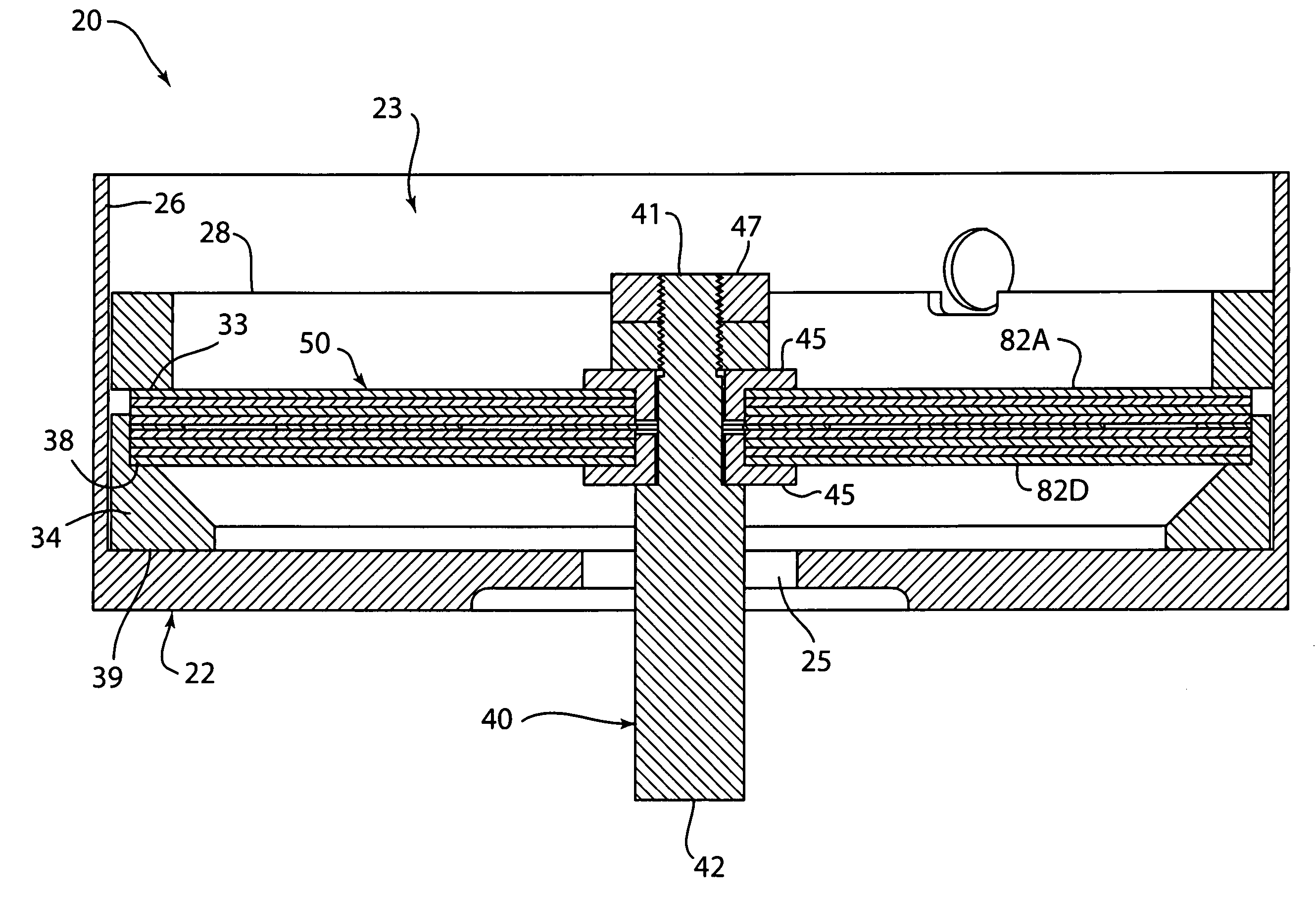
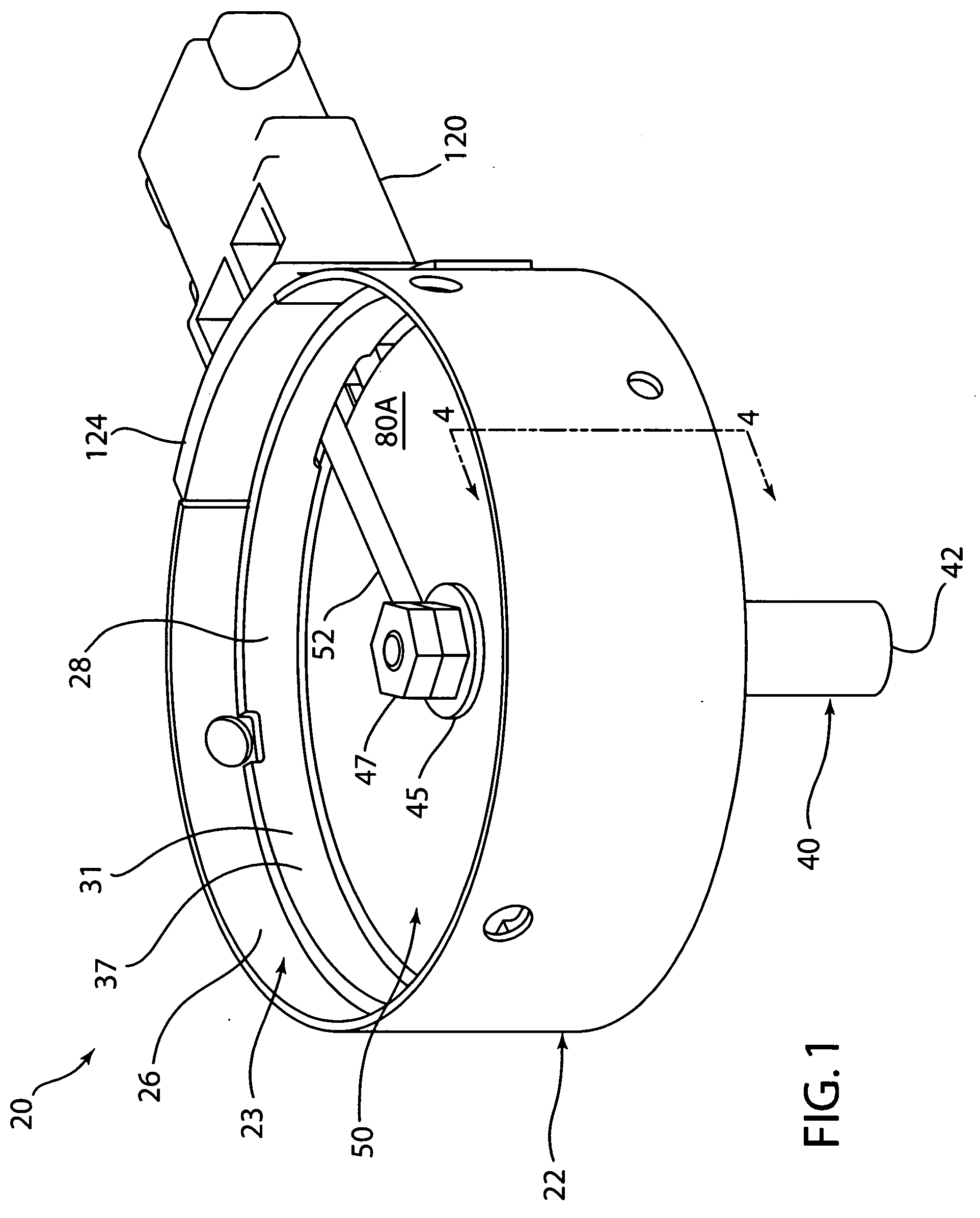
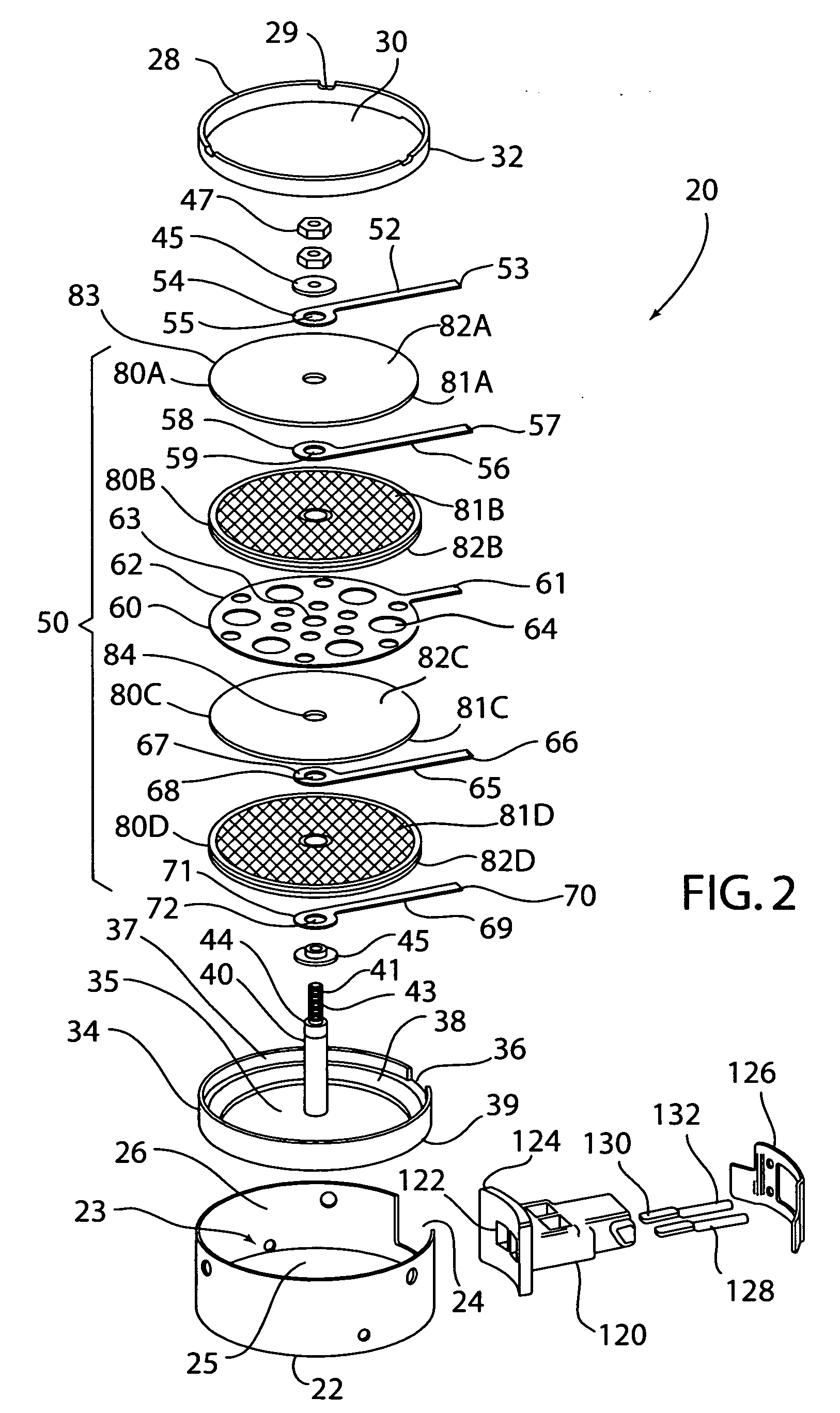
[0022] Referring to FIGS. 1-4, an embodiment of a piezoelectric bending actuator assembly 20 is shown. Piezoelectric bending actuator 20 has a cylindrical shaped housing 22. Housing 22 has a cavity 23, slot 24, hole 25 and an inner wall 26. A ring 28 is mounted in cavity 23. Ring 28 has a slot 29, a hole 30, an inner wall 31, outer wall 32 and bottom 33. Ring 28 is laser welded to inner wall 26 of housing 22. Inner wall 31 and bottom 33 are coated with an insulating material such as ceramic. Housing 22 and ring 28 can be made out of a metal such as stainless steel.

[0023] A retainer 34 is mounted in cavity 23. Retainer 34 has a hole 35, slot 36, lip 37, upper surface 38 and lower surface 39. Retainer 34 can be made out of a metal such as stainless steel. Retainer 34 can also be made out of plastic or ceramic.

[0024] A piezoelectric stack 50 is compressed and mounted in cavity 23 between ring 28 and retainer 34. Piezoelectric stack 50 has four curved or domed piezoelectric layers or ...


PUM


Abstract

A piezoelectric bending actuator that is insensitive to temperature changes. The actuator includes a pair of piezoelectric layers. One of the layers bends in response to an applied voltage and the other piezoelectric layer flattens in response to an applied voltage. The piezoelectric layers are mounted adjacent to each other. The piezoelectric layers move opposite to each other in response to a change in temperature such that the piezoelectric bending actuator is stable over a range of temperatures. The piezoelectric layers are held in compression between a ring and a retainer. Compressing the piezoelectric layers allows the bending actuator to have a high stroke with improved durability because the discs are kept in compression.

Description

BACKGROUND [0001] The present invention relates to actuators in general and in particular to a piezoelectric actuator that has a stable response over a wide range of operating temperatures. [0002] Piezoelectric devices alter their shape in response to an applied electric field. An electric field applied in the direction of polarization effects an expansion or contraction of the piezoelectric material in various directions. A voltage applied in the opposite direction of polarization causes a contraction or expansion of the material in those same directions. [0003] Piezoelectric bending actuators, such as thermally pre-stressed bending actuators curve or bend under an applied voltage. These actuators convert electrical energy into mechanical movement and / or force. Various bending actuators have been used. [0004] Unfortunately, the performance of piezoelectric bending actuators is quite temperature dependent. This limitation can present a problem in automotive or engine applications. A...

Claims


Application Information

Patent Timeline
Patent Type & Authority Applications(United States)
IPC IPC(8): H02N2/00H10N30/20
CPCH01L41/0973H01L41/0926H10N30/204
Inventor SCHLABACH, RODERIC A.
Owner CTS CORP ELKHART
Learn More