Vehicle interior illumination lamp

a technology for interior illumination and lamps, which is applied in the direction of contact members penetrating/cutting insulation/cable strands, coupling device connections, transportation and packaging, etc., can solve the problems of low efficiency of the operation for mounting the difficulty in achieving a compact size of the interior illumination lamp, etc., to achieve enhanced assembling operation and compact design

Inactive Publication Date: 2005-11-24
YAZAKI CORP
View PDF6 Cites 20 Cited by
  • Summary
  • Abstract
  • Description
  • Claims
  • Application Information

AI Technical Summary

Benefits of technology

[0010] This invention has been made in view of the above circumstances, and an object of the invention is to provide a vehicle interior illumination lamp in which the efficiency of an assembling operation is enhanced, and a compact design can be achieved.

Problems solved by technology

Therefore, because of the increased size of the integral bus bar 1, the efficiency of the operation for mounting the interior illumination lamp (employing the integral bus bar 1) in the housing was low, and besides it was difficult to achieve a compact size of the interior illumination lamp

Method used


Image

  • Vehicle interior illumination lamp
  • Vehicle interior illumination lamp
  • Vehicle interior illumination lamp

Examples


Embodiment Construction

[0032] A preferred embodiment of the present invention will now be described in detail with reference to the drawings.

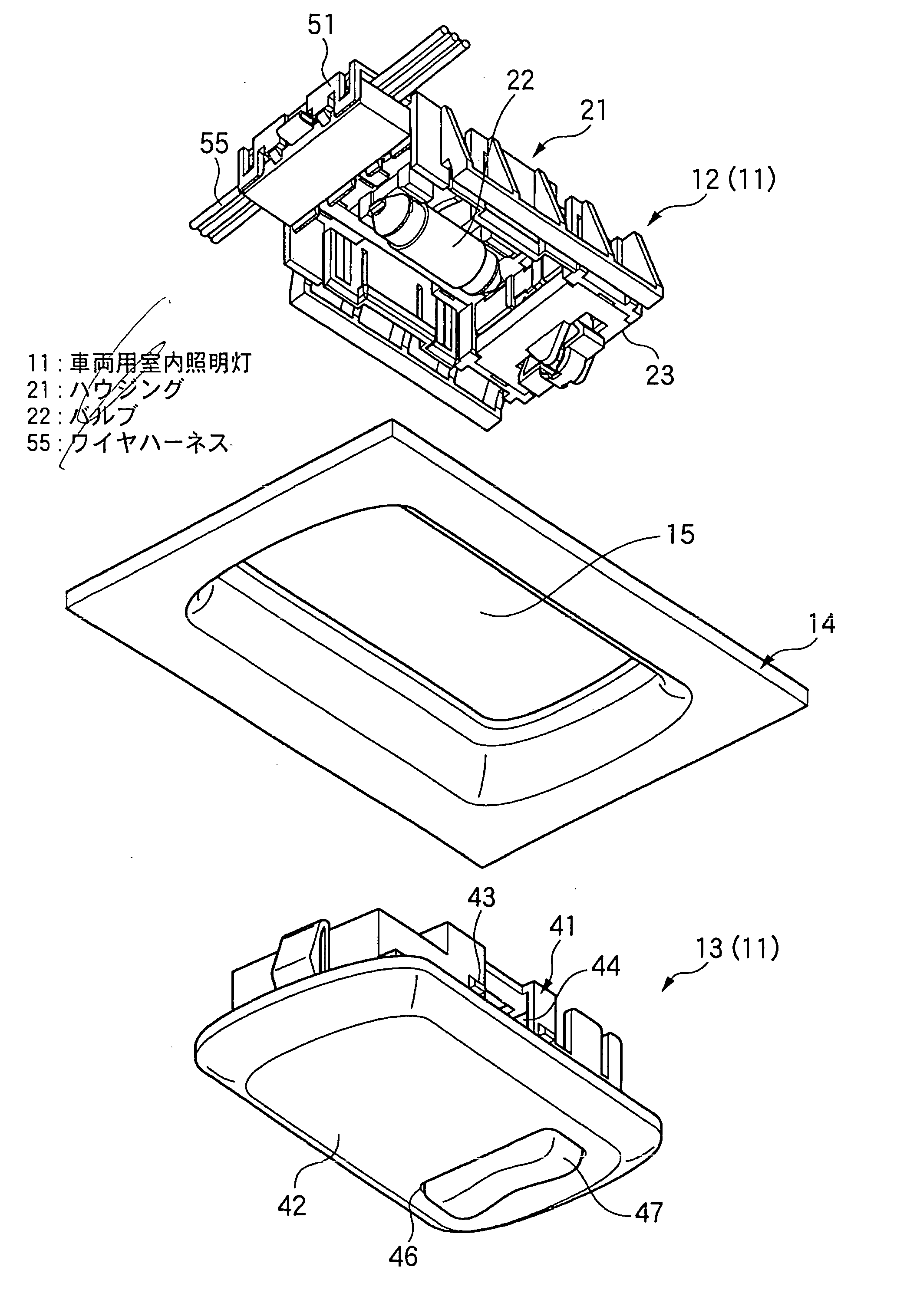
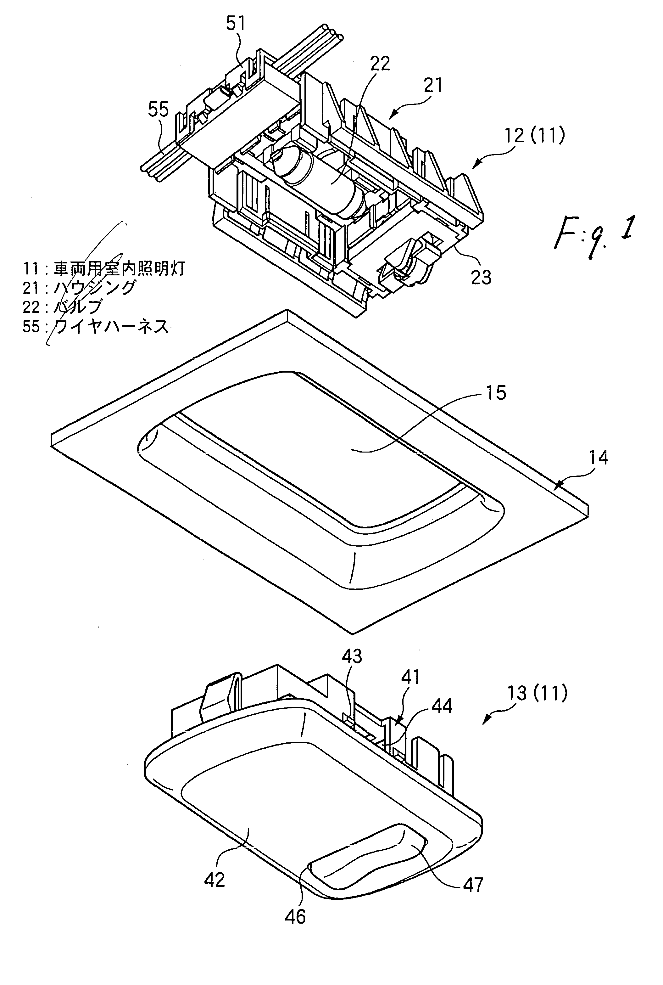
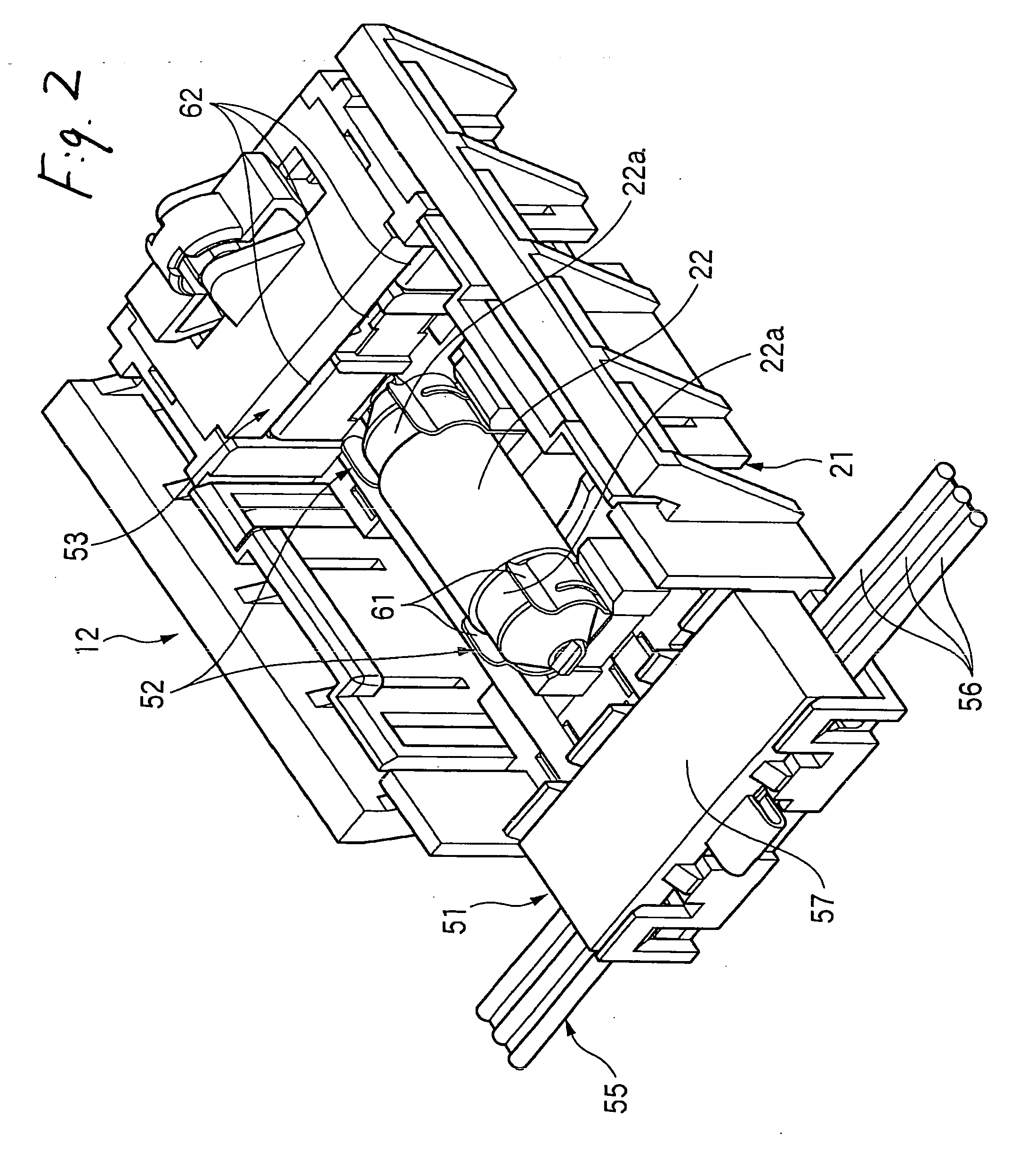
[0033]FIG. 1 is an exploded, perspective view of the preferred embodiment of a vehicle interior illumination lamp of the invention, showing its structure, FIG. 2 is a perspective view showing the structure of a function portion of the interior illumination lamp of FIG. 1, FIG. 3 is a perspective view showing the internal structure of the function portion of the interior illumination lamp of FIG. 1, FIG. 4 is a perspective view showing the shape of an integral bus bar to be mounted in the function portion of the interior illumination lamp of FIG. 1, and FIG. 5 is a plan view explanatory of a developed shape of the integral bus bar.

[0034] As shown in FIG. 1, the vehicle interior illumination lamp 11 comprises the function portion 12, and a design portion 13.

[0035] The function portion 12 is disposed at a reverse side of a ceiling plate 14 forming a ceiling of a vehi...


PUM


Abstract

An integral bus bar 81, having a plurality of wiring bus bars 50 formed integrally therewith, is mounted in a housing 81, and bridge portions 82, interconnecting the wiring bus bars 50, are cut, thereby separating the wiring bus bars. The integral bus bar 81 includes bulb holding portions 52 for respectively holding opposite end portions of a bulb, and each of the bulb holding portions includes a pair of holding piece portions 61 for holding the corresponding end portion of the bulb therebetween. The wiring bus bars 50 are arranged to extend in a direction of arrangement of the bulb which is to be held in the bulb holding portions 52. The holding piece portions 61 of each bulb holding portion 52 are bent respectively at opposite side edges of a support wall portion 83, extending upwardly from the corresponding wiring bus bar 50, in the direction of arrangement of the bulb, and are disposed in opposed relation to each other.

Description

BACKGROUND OF THE INVENTION [0001] 1. Field of the Invention [0002] This invention relates to a vehicle interior illumination lamp for mounting on a ceiling of a vehicle. [0003] 2. Related Art [0004] There is known the type of vehicle interior illumination lamp for mounting on a vehicle ceiling, in which an integral bus bar, formed by blanking and bending an electrically-conductive metal sheet, is incorporated in a resin-molded housing (see, for example, Unexamined Japanese Patent Publication 2001-180372). [0005] As shown in FIG. 8, this integral bus bar 1 includes contacts 2 forming a switch, an electrical connection portion 3 forming connecting portions for connection to a wire harness, and bulb holding portions 5 for respectively holding terminal portions (opposite end portions) of an incandescent bulb (hereinafter referred to merely as “bulb”) in electrically-connected relation thereto. The contacts 2, the electrical connection portions 4 and the bulb holding portions 5 are wire...

Claims


Application Information

Patent Timeline
Patent Type & Authority Applications(United States)
IPC IPC(8): B60Q1/00B60Q3/02
CPCB60Q3/0279B60Q3/0203B60Q3/74B60Q3/51
Inventor NAGAI, KENTAROHIRAYAMA, YOSHINORI
Owner YAZAKI CORP
Why Eureka
Try Eureka