Collapsible indoor television antenna assembly

a technology for indoor television and antennas, which is applied in the direction of antennas, antenna details, flexible aerials, etc., can solve the problems of waste of packaging materials, bulky boxes, and vhf and uhf antennas of conventional indoor television antennas that cannot be completely folded relative to the body, so as to save packaging materials and storage spa

Inactive Publication Date: 2005-11-24
TRANS ELECTRIC
View PDF1 Cites 7 Cited by
  • Summary
  • Abstract
  • Description
  • Claims
  • Application Information

AI Technical Summary

Benefits of technology

[0008] The main objective of the invention is to provide a compact indoor television antenna assembly that has collapsible VHF and UHF antennas for a size reduction when the television antenna assembly is not in use to save packaging materials and storage space.

Problems solved by technology

However, the VHF and UHF antennas of the conventional indoor television antenna cannot be completely folded relative to the body and hidden entirely by the body when not in use.
The conventional television antenna will need a bulky box to package the entire television antenna inside for storage, transport or selling.
Using the bulky box to package the television antenna will waste packaging materials and needs large storage space in stock rooms.
Furthermore, the package box for the conventional television antenna cannot have a specific shape and eye-catching design because the unfolded VHF and UHF antennas extend outward relative to the base.
The conventional television antenna packaged with a regular package box cannot attract consumers when the consumers want to purchase the indoor television antennas.

Method used


Image

  • Collapsible indoor television antenna assembly
  • Collapsible indoor television antenna assembly
  • Collapsible indoor television antenna assembly

Examples


Embodiment Construction

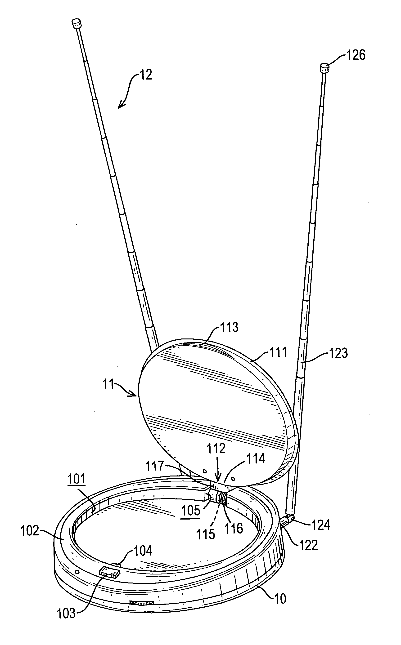
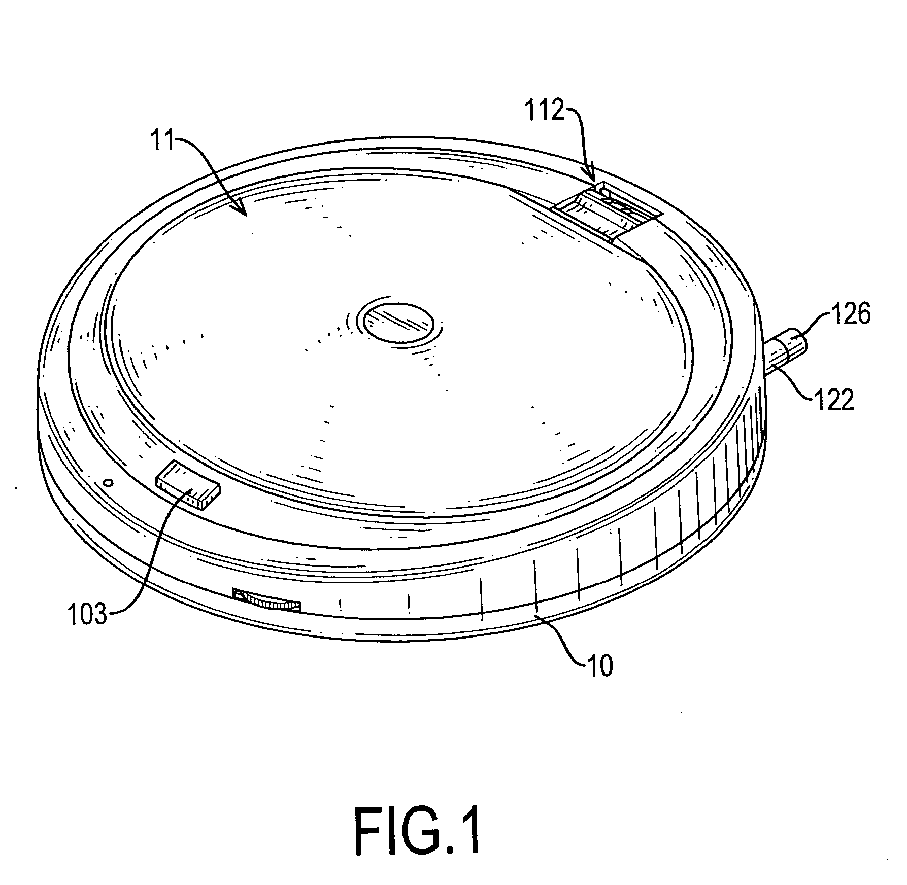
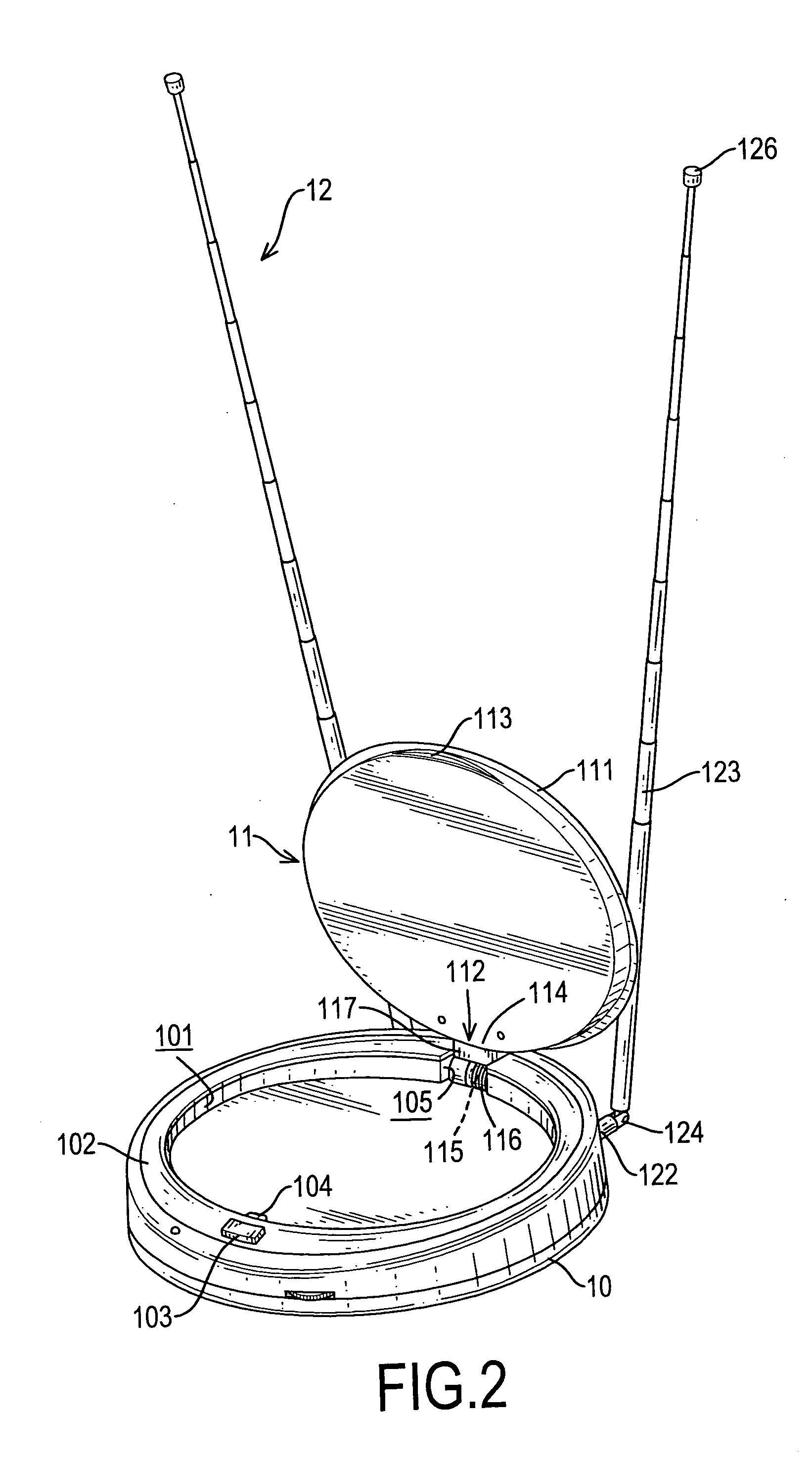
[0017] With reference to FIGS. 1, 2 and 3, an indoor television antenna assembly in accordance with the present invention comprises a base (10), a UHF antenna (11) and a VHF antenna set (12).

[0018] The base (10) is used to mount on a surface and comprises two casing portions. The base (10) may be shaped as a hollow thick disk and has a top, a bottom, a top recess (101) and an annular rib (102). The annular rib (102) is formed on the top of the base (10), defines the top recess (101) and has a pivot slot (105). The annular rib (102) comprises a release button (103) and a latch (104). The release button (103) connects to and retracts the latch (104) inward to the annular rib (102) as the release button (103) is pressed. The latch (104) is retractably mounted in the annular rib (102) and extends into the top recess (101) to engage the UHF antenna (11).

[0019] The base (10) further has two parallel inner tracks (106). The inner tracks (106) are formed along the interior of the base (10...


PUM


Abstract

A collapsible indoor television antenna assembly includes a base, a VHF antenna set and a UHF antenna. The base has a top, a top recess and an annular rib with a pivot slot formed on the top of the base to define the top recess. The UHF antenna includes a pivot assembly and a disk antenna. The pivot assembly is mounted in the pivot slot. The disk antenna is collapsible, is rotatably mounted on the pivot assembly and is received in the top recess. The VHF antenna set includes two connection rods and two collapsible dipole antennas. The connection rods are retractably and rotatably mounted in the base. The dipole antennas are pivotally connected to the connection rods and are retracted into the base. Consequently, the foldable UHF and VHF antennas make the entire indoor television antenna assembly compact to save packaging materials and storage space.

Description

BACKGROUND OF THE INVENTION [0001] 1. Field of the Invention [0002] The present invention relates to an indoor television antenna assembly, and more particularly to an indoor television antenna assembly having both a collapsible VHF antenna set and a collapsible UHF antenna to render the television antenna assembly compact when the UHF and VHF antennas are not in use. [0003] 2. Description of Related Art [0004] Indoor television antennas are connected to televisions for receiving television signals transmitted from television stations. The television signals operate generally at very high frequency (VHF) band and ultrahigh frequency (UHF) band. Therefore, a conventional television needs typically both VHF and UHF antennas to receive respectively the television signals provided at different bands. [0005] The conventional indoor television antenna in accordance with the prior art comprises a base, a VHF antenna set and a UHF antenna. The UHF and VHF antennas are attached to the base a...

Claims


Application Information

Patent Timeline
Patent Type & Authority Applications(United States)
IPC IPC(8): H01Q1/08H01Q1/10H01Q3/00
CPCH01Q1/106H01Q1/085
Inventor WANG, CHENG-SI
Owner TRANS ELECTRIC
Why Eureka
Try Eureka