Panoramic surveillance device

a technology of panoramic and camera, applied in the field of panoramic photographing equipment, can solve the problems of difficult correction of aberrations with software reprocessing, high cost of manufacturing, and insatiable solutions using aspherical lenses

Inactive Publication Date: 2005-11-24
GLOBAL VISION HLDG
View PDF5 Cites 16 Cited by
  • Summary
  • Abstract
  • Description
  • Claims
  • Application Information

AI Technical Summary

Problems solved by technology

Solutions using aspherical lenses are not satisfactory because the cost of manufacturing them is very high and the aberrations difficult to correct with software reprocessing.
The solution is intended for photographing over 360°, but it produces images that are poor for video surveillance.
In fact, the panoramic images do not permit the correct apprehendsion of the details of the field covered and, thus, do not permit realization of an efficient video surveillance.
That solution produces satisfactory images, but has the disadvantage of leaving non-visualized zones during sweeping.

Method used


Image

  • Panoramic surveillance device
  • Panoramic surveillance device
  • Panoramic surveillance device

Examples


Embodiment Construction

[0015] It will be appreciated that the following description is intended to refer to specific embodiments of the invention selected for illustration in the drawings and is not intended to define or limit the invention, other than in the appended claims.

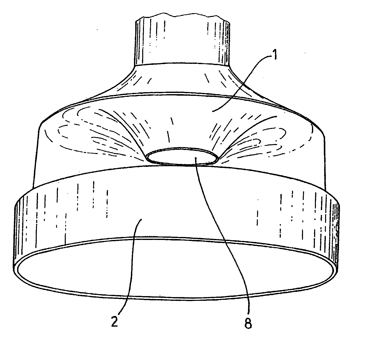
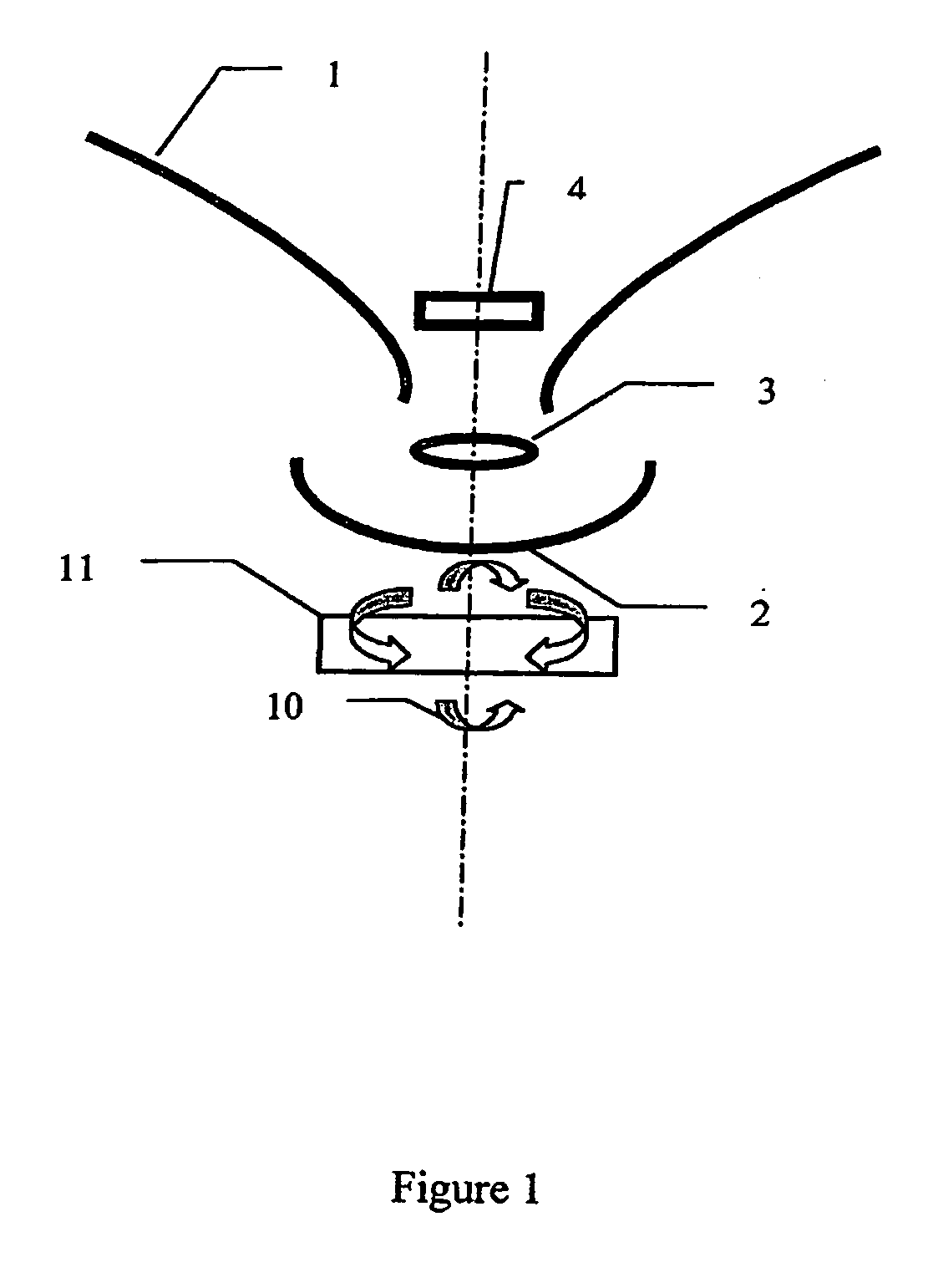
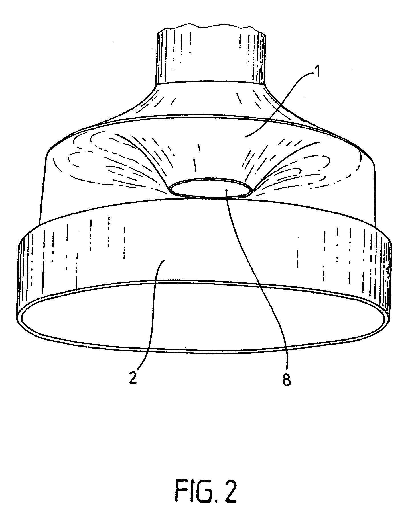
[0016] The invention relates in a general sense to a piece of equipment for video surveillance comprising optical means for forming a panoramic image and the acquisition of this panoramic image by a camera that transmits video information to a remote viewing station, characterized in that this piece of equipment also comprises means of acquiring an image with a non-panoramic angular opening included in the panoramic photographing field, the orientation of which acquisition means is controlled relative to the field of panoramic optical means as a function of a zone of interest detected in this panoramic image.

[0017] The acquisition means is advantageously constituted of an additional mobile camera along at least one axis of rotation....


PUM


Abstract

A video surveillance apparatus including an optical device that forms a panoramic image and acquisition of the panoramic image by a camera that transmits video information to a remote viewing station, and a device that acquires an image with a non-panoramic angular opening included in a panoramic photographing field, the orientation of the acquisition device being controlled relative to the field of panoramic optical device as a function of a zone of interest detected in the panoramic image.

Description

RELATED APPLICATION [0001] This is a continuation of International Application No. PCT / FR2003 / 003397, with an international filing date of Nov. 14, 2003 (WO 2004 / 046783 A1, published Jun. 3, 2004), which is based on French Patent Application Nos. 02 / 14308, filed Nov. 15, 2002, 03 / 03788, filed Mar. 27, 2003, and 03 / 04551, filed Apr. 11, 2003.FIELD OF THE INVENTION [0002] This invention relates to the area of panoramic photographing equipment, especially for video surveillance. BACKGROUND [0003] Various solutions for photographing at a very large angle are known. Solutions using aspherical lenses are not satisfactory because the cost of manufacturing them is very high and the aberrations difficult to correct with software reprocessing. [0004] The use of mirrors that deform with an optical or software anamorphic treatment is also known. By way of example, WO 95 / 06303 discloses a surveillance system for monitoring a space comprising a single camera and a convex mirror of the dome type. ...

Claims


Application Information

Patent Timeline
Patent Type & Authority Applications(United States)
IPC IPC(8): G02B13/06G02B17/06G02B17/08G08B13/193
CPCG08B13/193G02B13/06H04N23/55H04N23/60H04N23/698H04N7/18G03B37/00G02B17/00
Inventor BERDUGO, MARC
Owner GLOBAL VISION HLDG
Why Eureka
Try Eureka