Bumper device for data storage apparatus

Inactive Publication Date: 2005-11-24
SEAGATE TECH LLC
19 Cites 5 Cited by

AI-Extracted Technical Summary

Problems solved by technology

The interface between the heads and the disc surface is extremely delicate.
Disc drive systems occasionally experience external shock loads, for example, by the user hitting the drive or dropping the drive prior to or during handling while installing the drive in a host device such as a computer ca...

Method used

[0014] The base plate 18 and the PCBA 14 have a generally rectangular configuration with corners 26. Bumpers 24 are attached to the PCBA 14 proximate the corners 26. The bumpers 24 are used to reduce the impact of externally introduced shock inputs to the PCBA and HDA. Such shock inputs occur during handling and/or installation of the disc drive apparatus within a host device such as a computer cabinet. Typically, when the disc drive apparatus is dropped or accidentally bumped against a hard surface, the corners 26 of the PCBA 14 that receive the shock input.
[0015] Such shock inputs are transmitted through the housing to the heads 28 and actuator arms 30 of the actuator assembly 22. Transmission of the shock may misalign the actuator arms 30 or cause th...

Benefits of technology

[0006] The present invention includes a bumper attached to a data storage apparatus for dampening externally originated shock loads. The data storage apparatus comprises a transducer assembly having a base. A printed circuit board is attached to the base. At least one bumper is attached to at the circuit board. The bumper reduces the shock to the transducer assembly and printed circuit board assembly that may be encountered in transport or in installation of the data storage apparatus into a host device such as a computer cabin...

Abstract

A bumper device is attached to a data storage apparatus for dampening externally originated shock loads. The disc drive apparatus comprises a base, a transducer assembly, and a printed circuit board assembly. The printed circuit board assembly is attached to an exterior surface of the base, and a bumper device is attached to the circuit board to engage external surfaces and to absorb shock loads created by an impact from such external surfaces.

Application Domain

Technology Topic

Image

  • Bumper device for data storage apparatus
  • Bumper device for data storage apparatus
  • Bumper device for data storage apparatus

Examples

  • Experimental program(1)

Example

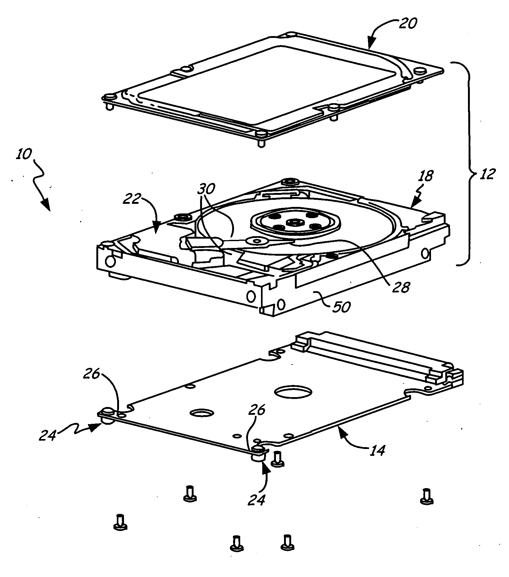
[0012] A disc drive apparatus of the present invention is generally indicated at in FIG. 1. Although a disc drive assembly is specifically illustrated, the present invention is applicable to other data storage devices such as a tape drive assembly having a moving transducer assembly to read data from a storage medium other than a disc. The disc drive apparatus 10 includes a head disc assembly (HDA) 12 and a printed circuit board assembly 14 (PCBA). The HDA 12 includes a base plate 18 and a top cover 20 secured together with a plurality of screws. The PCBA 14 is secured to the underside of the base plate 18. The PCBA 14 typically contains the drive control electronics circuitry and interface components for interfacing the disc drive apparatus 10 with other computer elements.
[0013] The HDA includes an actuator assembly 22 positioned on the base plate 18 under the cover 20. The actuator assembly includes a pair of heads 28 (one of which is shown) and actuator arms 30. The number of heads 28 and actuator arms 30 may vary depending on the number of discs that are employed within the disc drive apparatus 10. The particular configuration of the HDA 12 illustrated in the drawings is for exemplary purposes only and other configurations are included within the present invention.
[0014] The base plate 18 and the PCBA 14 have a generally rectangular configuration with corners 26. Bumpers 24 are attached to the PCBA 14 proximate the corners 26. The bumpers 24 are used to reduce the impact of externally introduced shock inputs to the PCBA and HDA. Such shock inputs occur during handling and/or installation of the disc drive apparatus within a host device such as a computer cabinet. Typically, when the disc drive apparatus is dropped or accidentally bumped against a hard surface, the corners 26 of the PCBA 14 that receive the shock input.
[0015] Such shock inputs are transmitted through the housing to the heads 28 and actuator arms 30 of the actuator assembly 22. Transmission of the shock may misalign the actuator arms 30 or cause the heads to vibrate and move to the point where a head may impact the surface of the disc to scratch the disc or damage the head, or both. In one embodiment of the invention, the actuator assembly 22 is located approximate to the end of the apparatus itself with bumpers 24. The bumpers 24 of the present invention reduce greatly the impact of such shocks on the actuator assembly 22 as well as other components by absorbing the energy input from the shock at a lower cost than prior art gaskets. In addition, the bumpers 24 provide design flexibility since no design changes to the disc drive apparatus itself need to be made to accommodate the bumpers 24. Further, the bumpers 24 do not act as an obstacle to any future design changes in the described apparatus.
[0016] As best illustrated in FIGS. 2 and 3, the bumpers 24 are attached to the PCBA 14 by a frictional fit within slots 34 located at the two corners 26 of the PCBA 14. Fingers 44 and 46 define the slots 34. The bumpers 24 have a generally cylindrical shape with an annular slot 36 located between a base facing portion 38 and outwardly extending portion 40. The annular slot 36 is defined by opposite facing surfaces 39 and 41 of the base facing portion 38 and the outwardly extending portion, respectively. The annular slot 36 with surfaces 39 and 41 frictionally engage the fingers 44 and 46.
[0017] The base engaging portion 38 is positioned within a well 42 of the base 18. The outwardly extending portion 40 extends a distance preferably that is at least as high as a rail section 50 of the base 18. The outwardly extending portion 40 needs to be of at least a height of the rail portion 50 to ensure that the bumpers 24 are the first elements of the apparatus 10 that are engaged in any contact with an external surface that may cause a shock load. Likewise, the position of the bumpers 24 proximate a corner of the PCBA is such that the bumpers 24 are to be engaged before the PCBA or the base 18 when the corners 26 come in contact with another surface.
[0018] One material found suitable for the bumper of the present invention is a fluoroelastomer (FE 56210) sold by Dyneon, a subsidiary of 3M Company of St. Paul, Minn. The particular fluoroelastomer used has a durometer of approximately 60±5 shore “A”, a tensile strength of approximately 1350 psi, an elongation of approximately 250%, a modulus of approximately 260 psi at 0% and a compression set of approximately 20%. However, other types of materials such as other elastomers or rubbers that absorb and dissipate energy from shock impacts are included within the present invention.
[0019] One method of determining the dampening effect of the present invention is a drop test in which the disc drive apparatus is positioned with the PCBA 14 facing downwardly. The end of the disc drive apparatus opposite from the bumpers 24 is pivotally held while the other end of the disc drive apparatus containing the bumpers 24 is free to move. The actuator assembly 22 is located proximate the end that has the bumpers 24. The disc drive apparatus is permitted to swing about the pivot with the end of the disc drive apparatus containing the bumpers hitting a hard surface. An accelerometer is positioned on the disc drive apparatus proximate the actuator assembly location. The end of the disc drive apparatus that has the bumpers was raised to a 45° angle above a horizontal plane running through the pivot point and permitted to drop (pivot) until the bumper end hits the hard surface.
[0020]FIG. 4 graphically illustrates a comparative test performed with the disc drive apparatus being dropped without the bumpers 24 (broken lines), and with the bumpers 24 (solid line). As FIG. 4 illustrates, the impact response in G-force was reduced three times when using the bumpers 24 of the present invention. In addition, the duration of the impact response (initial peak) when bumpers were used was increased 10 fold to about 2 milliseconds when compared to the disc drive apparatus without bumpers (broken lines) that had a shorter impact response with a higher peak.
[0021] Although the present invention has been described with reference to preferred embodiments, workers skilled in the art will recognize that changes may be made in form and detail without departing from the spirit and scope of the invention.
[0022] It is to be understood that even though numerous characteristics and advantages of various embodiments of the invention have been set forth in the foregoing description, together with details of the structure and function of various embodiments of the invention, this disclosure is illustrative only, and changes may be made in detail, especially in matters of structure and arrangement of parts within the principles of the present invention to the full extent indicated by the broad general meaning of the terms in which the appended claims are expressed. For example, the particular elements may vary depending on the particular application for the disc drive system while maintaining substantially the same functionality without departing from the scope and spirit of the present invention. Features shown in one embodiment can be appropriately adapted to other embodiments within the scope of the invention. In addition, although the preferred embodiment described herein is directed to a disc drive assembly and the use of at least one bumper to absorb external shock loads, it will be appreciated by those skilled in the art that the teachings of the present invention can be applied to other sensitive miniature devices, without departing from the scope and spirit of the present invention.

PUM

no PUM

Description & Claims & Application Information

We can also present the details of the Description, Claims and Application information to help users get a comprehensive understanding of the technical details of the patent, such as background art, summary of invention, brief description of drawings, description of embodiments, and other original content. On the other hand, users can also determine the specific scope of protection of the technology through the list of claims; as well as understand the changes in the life cycle of the technology with the presentation of the patent timeline. Login to view more.

Similar technology patents

Deep water stone throwing method and device

InactiveCN104988926AReduce shockDeep waterFoundation engineeringEngineeringFall detection
Owner:SHENZHEN OFFSHORE OIL ENG UNDERWATER TECH

Automobile dual-mass flywheel with continuous varied stiffness and high torque

InactiveCN102230512AReduce shockAvoid shock loads and noiseFlywheelsFlywheelHigh torque
Owner:CHONGQING UNIV

Classification and recommendation of technical efficacy words

Why Eureka
Try Eureka