
Storage container lighting system

a storage container and lighting technology, applied in the field of portable lighting systems, can solve the problems of reducing the ability of users to locate, move or retrieve items from within storage containers, affecting the safety of users, and reducing the ability of users to aim lights, etc., to achieve convenient installation, save battery life, and not sensitive to vibration

Inactive Publication Date: 2005-11-24
PETERSEN STEVEN D
View PDF9 Cites 7 Cited by
  • Summary
  • Abstract
  • Description
  • Claims
  • Application Information

AI Technical Summary

Benefits of technology

[0025] (k) some existing storage container lighting systems are restricted to white light; the present invention allows use of colored LED lamps.
[0026] Prior art does not provide a system with a tilt-sensitive ON OFF switch along with a manual switch to conserve battery life. Prior art does not provide bright white LED lamps that are durable and are not sensitive to vibration. Prior art does not provide for removal of lighting device from a mounting location for use outside a storage container. Prior art does not allow for use of colored lamps for use in specialized situations, such as a red lamp for use in an emergency situation.
[0038] (11) screws to mount base to a storage container cover, when tape will not stick to certain surfaces, including fiberglass and fabric-covered surfaces of tonneau covers.
[0049] (k) to provide coverable storage con

Problems solved by technology

At night, or in a dark location, retrieving items from such containers becomes difficult due to lack of light.
This lack of light is dangerous due to sharp blades and pieces commonly associated with power and hand tools.
In hazardous situations, such as a flat tire at night, a convenient source of light in the problem area is not provided by vehicle manufacturers.
When a conventional flashlight is used, one hand is needed to hold it, reducing the ability of a user to locate and move or retrieve items from within a storage container, or to aim a light where it is needed in the case of a mechanical failure.
Certain automobile trunks lack lighting to illuminate the inside of the trunk restricting the safe and efficient addition, retrieval, or movement of items contained in such trunks.
Often, power is unavailable where the container is located, so when light is needed conventional lights cannot be used.
Handheld lights restrict the handling of items to be stored.
The following is a description and the disadvantages of these various known methods of providing light in storage containers:
The light in Willis U.S. Pat. No. 6,227,677 is not well suited for storage containers, such as a toolbox, for several reasons.
The light disclosed is not equipped with a tilt-sensitive switch; therefore, automatic operation is not possible.
The light does not provide convenient mounting methods that would allow removal of the light for emergency use.
The light in Roberts, et al U.S. Pat. No. 5,347,440 is not well suited for storage containers, such as a toolbox, for several reasons.
The light disclosed in Roberts, et al U.S. Pat. No. 5,347,440 is not equipped with a tilt-sensitive switch; therefore, automatic operation is not possible.
The removal of the lamp unit from the body of the light disclosed in Roberts, et al U.S. Pat. No. 5,347,440 prohibits electrical power from reaching the lamp and thus cannot be used in a location where the lamp body is not available.
Incandescent bulbs utilized in this device are inefficient, compared to Light Emitting Diode (LED) lamps, resulting in a device with a short battery life.
Incandescent bulbs are sensitive to vibration and breakage, so do not lend themselves to the rugged environment associated with a work truck or storage container.

Method used


Image

  • Storage container lighting system
  • Storage container lighting system
  • Storage container lighting system

Examples


Embodiment Construction

[0066] It is an object of the Storage Container Lighting System to provide one or more of the following desirable features not heretofore known or used.

Description—FIG. 1—Preferred Embodiment

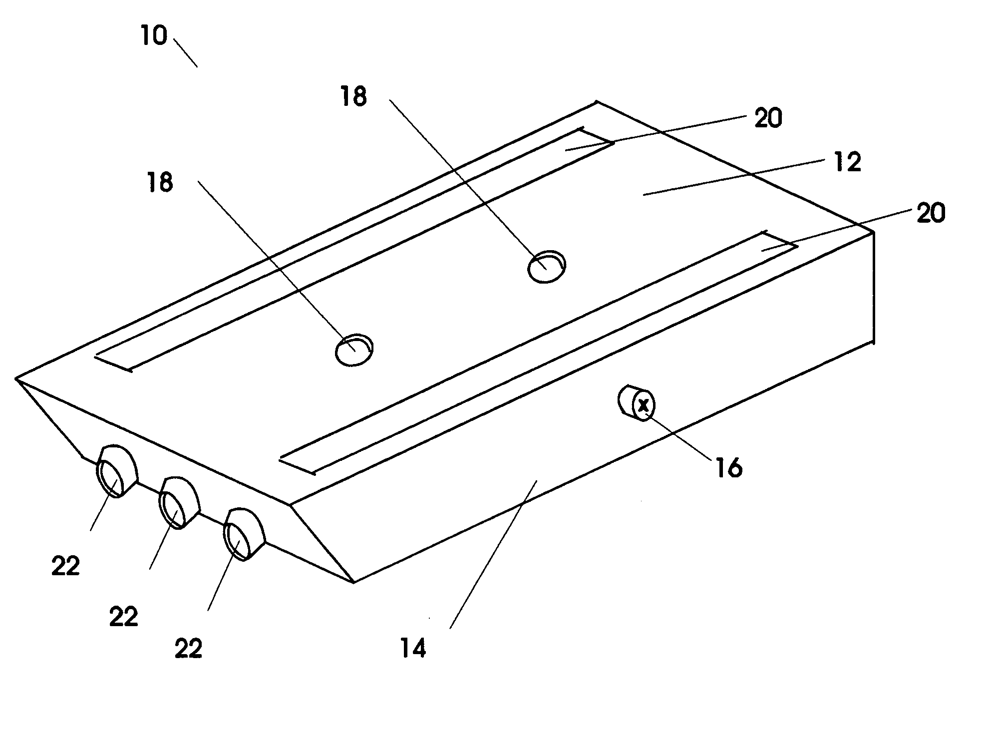
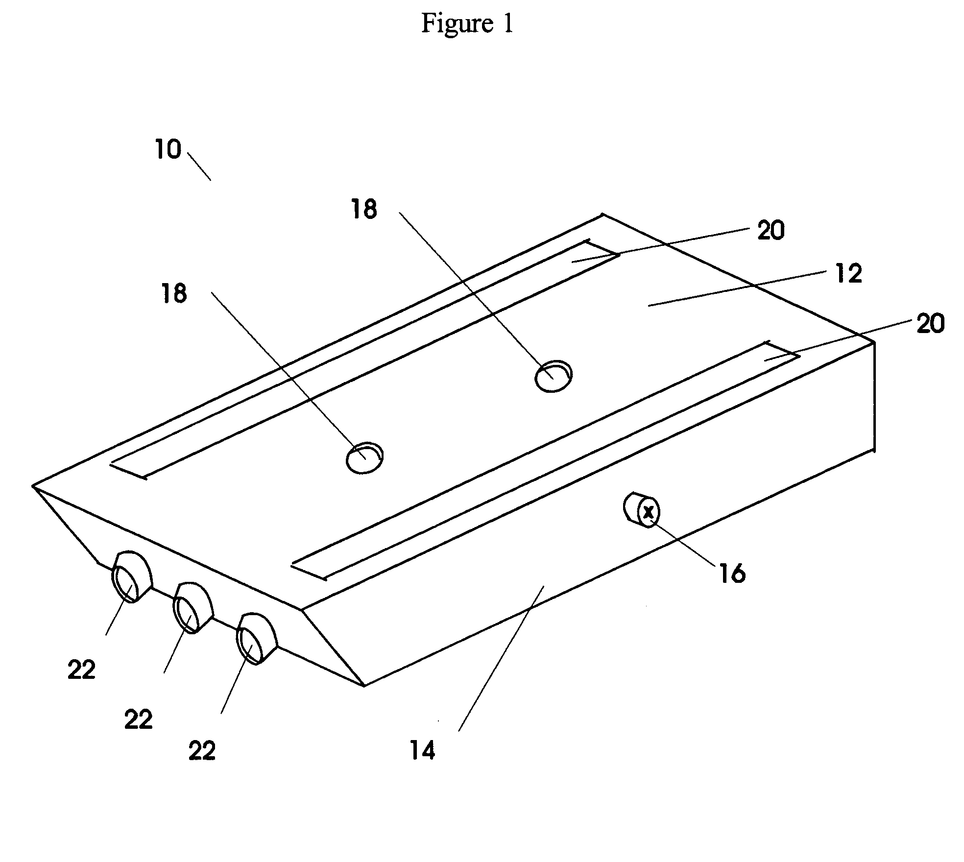
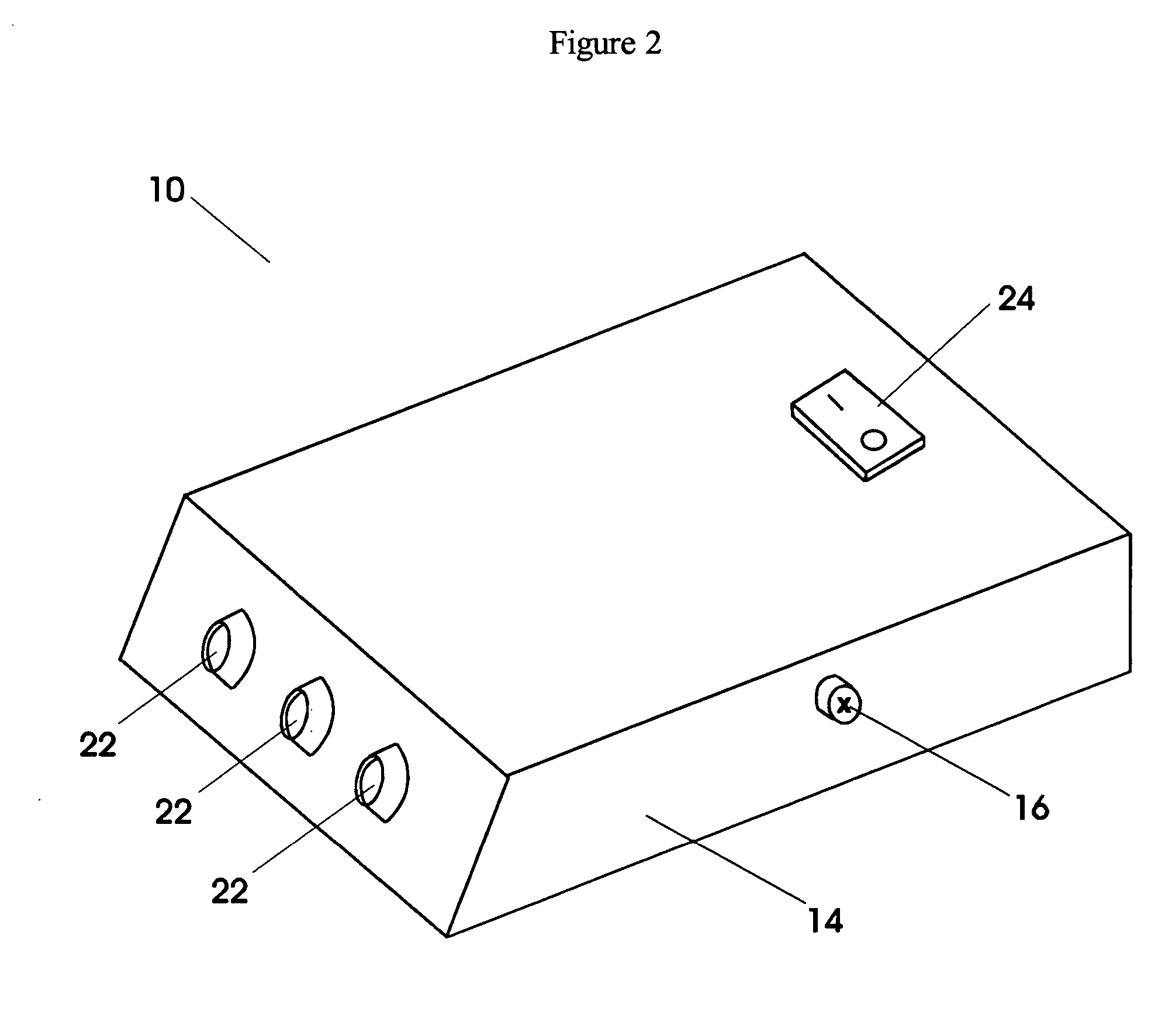
[0067]FIG. 1 is perspective view showing formed base 12 of Storage Container Lighting System 10. Thumb screw 16 located on side near the center of Lighting System 10 secures formed module 14 to base 12. A second thumb screw 16 is located in a similar location on the opposite side of module 14. (See FIG. 5)

[0068] One option for attaching base 12 to a container cover or other fixed location is to use double-sided foam tape 20 on surface of base 12 to adhere Lighting System 10 to fixed location. Another option for attaching base 12 to a container cover or other fixed location is to bore mounting holes 18 into surface of base 12 for use in attaching base 12 with screws to a fixed location. Three Light Emitting Diode (LED) lamps 22 on one end of module 14 are automatically activated when Lighting ...


PUM


Abstract

A Storage Container Lighting System 10 that is a battery-powered light with automatic ON and OFF function activated by raising or lowering a storage container cover 30 or other surface to which it is attached. Angle of activation is adjustable. System 10 has portability capability. System 10 provides light through use of low current, high-intensity white light emitting diodes 22. System 10 allows for different colored lamps for specialized applications. Tilt-activated switch 26 activates light when storage container cover 30 is raised and turns off light when cover 30 is lowered. Rocker switch 24 is provided so lights can be turned off when cover 30 is left open for extended period of time. Standard household batteries 42 serve as a power supply. Module 14, a low profile enclosure, houses electronic components. Module 14 slides into base 12. Base 12 is mounted to a container cover or other surface using either double-sided foam tape 20 or optional screws through mounting holes 18. Thumb screws 16 allow removal of module 14 from base 12 for use as a light source in another location.

Description

CROSS-REFERENCE TO RELATED APPLICATION [0001] This application claims the benefit of Provisional Patent Application Ser. No. 60 / 573,179 filed 2004, May 21.BACKGROUND [0002] 1. Field of the Invention [0003] The present invention relates to portable lighting systems for coverable storage containers. COPYRIGHT NOTICE [0004] A portion of the disclosure of this patent document contains material that is subject to copyright protection. The copyright owners have no objection to the facsimile reproduction by anyone of the patent document or the patent disclosure as it appears in the U.S. Patent and Trademark Office patent file or records, but otherwise reserves all copyrights whatsoever. BACKGROUND [0005] 2. Description of Prior Art [0006] A pickup truck or other vehicle can be equipped with covered storage containers permanently attached or placed in the vehicle. The storage container can hold a variety of items such as power and hand tools, and supplies. At night, or in a dark location, r...

Claims


Application Information

Patent Timeline
IPC IPC(8): B60Q3/06F21V33/00
CPCB60Q3/065F21Y2101/02F21V33/0084F21Y2115/10B60Q3/35
Inventor PETERSEN, STEVEN D.
Owner PETERSEN STEVEN D
Learn More