Methods and apparatus for facilitating cable locating

a technology of fiber optic cables and methods, applied in the field of fiber optic cables, can solve the problems of time-consuming process typically accomplished by highly skilled field technicians at a significant cos

Active Publication Date: 2005-11-24
CORNING OPTICAL COMM LLC
View PDF25 Cites 150 Cited by
  • Summary
  • Abstract
  • Description
  • Claims
  • Application Information

AI Technical Summary

Problems solved by technology

This time consuming process is typically accomplished by

Method used


Image

  • Methods and apparatus for facilitating cable locating
  • Methods and apparatus for facilitating cable locating
  • Methods and apparatus for facilitating cable locating

Examples


Embodiment Construction

[0022] The present invention will now be described more fully hereinafter with reference to the accompanying drawings in which exemplary embodiments of the invention are shown. However, this invention may be embodied in many different forms and should not be construed as limited to the embodiments set forth herein. Like reference numbers refer to like elements throughout the various drawings.

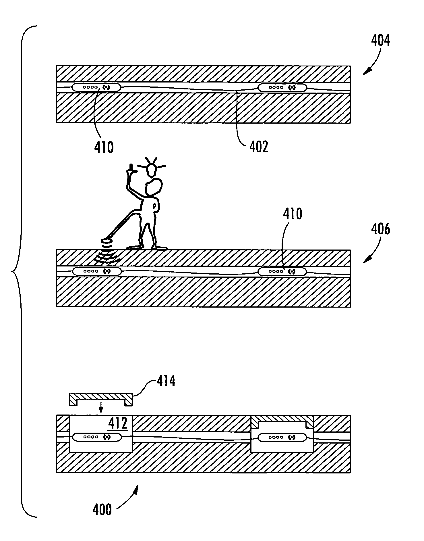
[0023] In some embodiments, a fiber optic cable, e.g., a preterminated cable, comprises a plurality of access locations at spaced apart locations along the cable length, thus providing multiple access locations, or tap points, for joining at least one drop cable to the distribution cable in the field. The exemplary preterminated fiber optic distribution cable may be wound upon a reel for distribution and deployment in buried applications, such as within a bore or conduit. The preterminated cable system is manufactured in a factory, thus eliminating the need for first installing a fiber optic ca...


PUM


Abstract

A method of laying an at least partially buried fiber optic cable includes placing a fiber optic cable with at least one associated alternating electromagnetic field emitting locating transponder (AEFELT) underground such that at least one AEFELT is buried underground.

Description

CROSS REFERENCE TO RELATED APPLICATION [0001] This application is a continuation-in-part (CIP) of U.S. patent application Ser. No. 10 / 852,427 filed May 24, 2004 titled Distributed Cable Assembly Having Overmolded Mid-span Access Location, which is hereby incorporated in its entirety.BACKGROUND OF THE INVENTION [0002] 1. Field of the Invention [0003] The present invention relates generally to a fiber optic cable and, more particularly, to methods and apparatus for facilitating the locating of a buried fiber optic cable. [0004] 2. Description of the Related Art [0005] Optical fibers are used for a variety of applications including voice communication, data transmission and the like. With the ever-increasing need for connecting remote locations to a fiber optic distribution cable, more efficient methods of performing a mid-span access of a distribution cable are required. Typically, to facilitate performing a mid-span access in the field, hand holes are dug and a horizontal bore is mad...

Claims


Application Information

Patent Timeline
IPC IPC(8): G02B6/44
CPCG01V15/00G02B6/4475G02B6/447G02B6/562
Inventor ELKINS, ROBERT B. IINIELSEN, LARS K.LUTHER, JAMES P.THEUERKORN, THOMASHURLEY, WILLIAM C.JACKMAN, WILLIAM S.OTT, MICHAEL J.
Owner CORNING OPTICAL COMM LLC
Why Eureka
Try Eureka