Composite pillow

a pillow and pillow body technology, applied in the field of composite pillows, can solve the problems of uneven level, difficult to locate parts of different materials or hardnesses at proper positions, etc., and achieve the effect of avoiding the possibility of sliding off from other parts and being easy to manufactur

Inactive Publication Date: 2005-12-01
DOKUTA ERU
View PDF11 Cites 22 Cited by
  • Summary
  • Abstract
  • Description
  • Claims
  • Application Information

AI Technical Summary

Benefits of technology

[0017] Furthermore, the central part presses from the upper portion against the contact portion of the holding part located in the lower portion, due to the load of a head applied onto the center of the composite pillow, the central part and the holding part are tightly fixed to each other, thereby eliminating the possibility of sliding off from other part even by a simple fixation method.
[0018] In accordance with the third aspect of the invention, the central part is divided into the neck side part and the head top side part contacting the neck side part by a face pair; both parts differ in hardness or material; and the contact surface of the neck side part and the head top side part arranged parallel in contact on the contact surface is diagonally formed. This enables the composite pillow to be easily manufactured for protecting a neck and a cervical vertebra, difference between the neck side part and the head top side part in level being imperceptible.

Problems solved by technology

In such a pillow, it is extremely difficult to locate parts of different materials or hardnesses at proper positions.
Also, although the pillow in which divided parts of a core material are arranged in a horizontal direction as shown in Japanese Unexamined Patent Publication No. 2003-144286 and the pillow in which a plurality of rooms are arranged in parallel, and a core material is filled thereinto as shown in Japanese Unexamined Patent Publication No. 2003-180499 can be set up accurately and minutely, since the contact surface between adjacent divided parts of a core material is almost perpendicular, there are drawbacks in that it brings about discomfort such that difference occurs in level when the levels of hardness are different between the parts, and such that a depression is formed by the divided parts of a core material being separated from each other when used.

Method used


Image

  • Composite pillow
  • Composite pillow
  • Composite pillow

Examples


Embodiment Construction

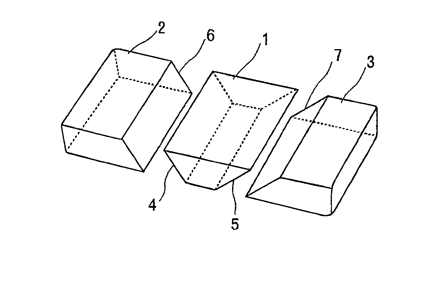
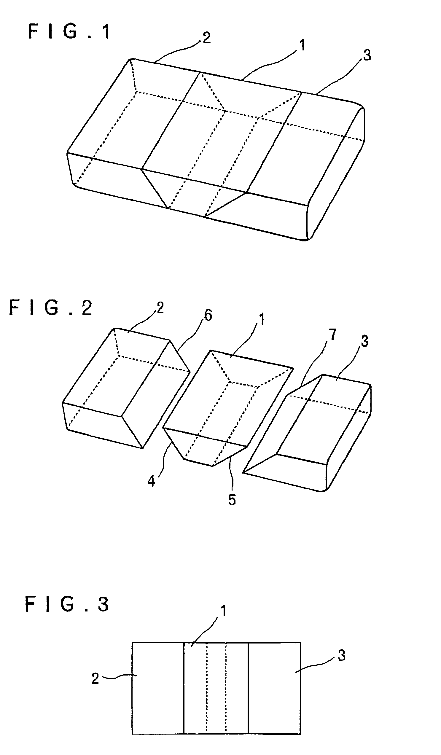
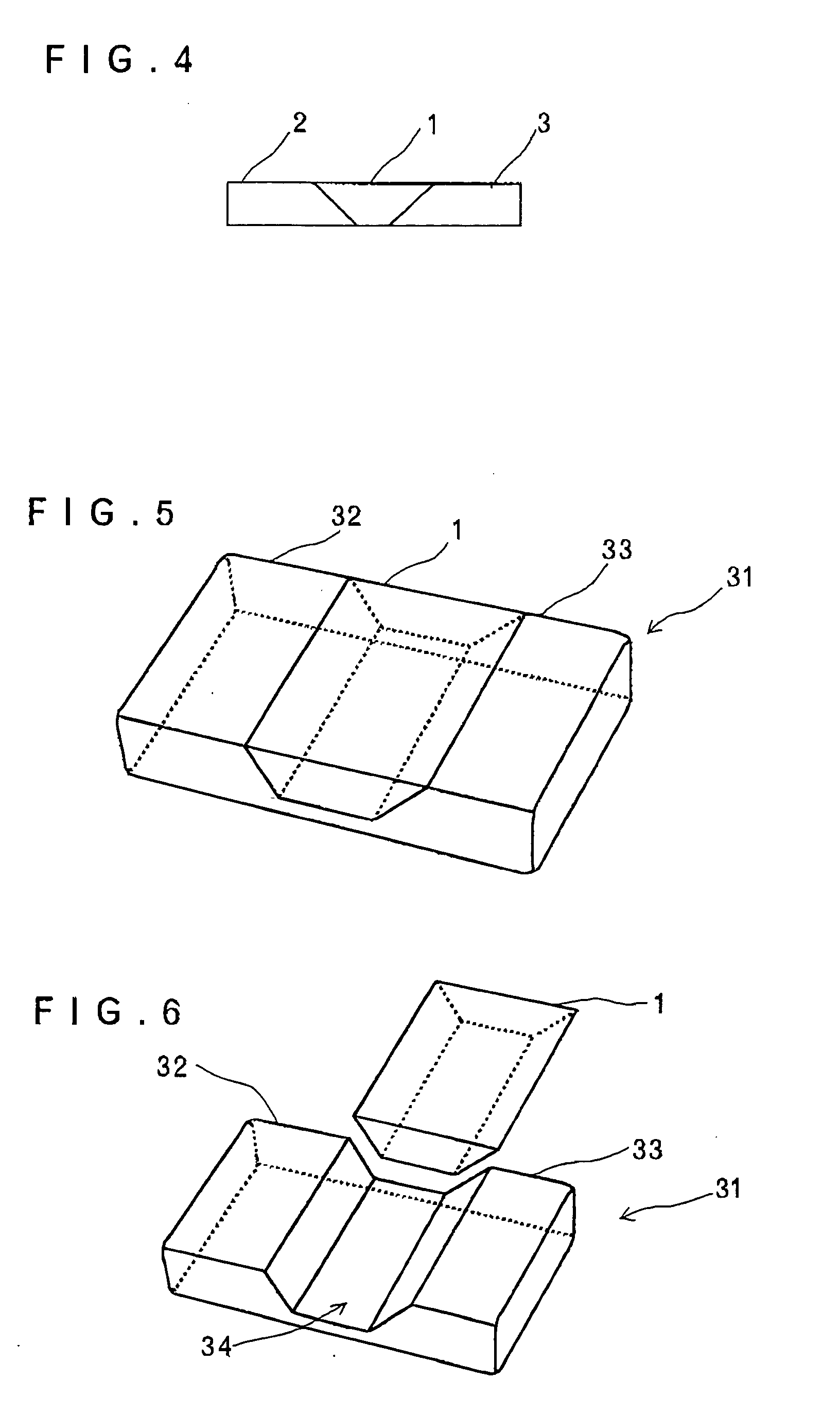
[0039] In the following, embodiments and best modes for carrying out the present invention will be described with reference to the drawings. FIG. 1 is a perspective view showing a composite pillow according to a first embodiment; FIG. 2 is an exploded perspective view showing the composite pillow according to the first embodiment; FIG. 3 is a plan view showing the composite pillow according to the first embodiment; and FIG. 4 is a front view showing the composite pillow according to the first embodiment.

[0040] The composite pillow according to the first embodiment, which corresponds to claims 1 and 2, is divided into a central part 1, and a left holding part 2 and a right holding part 3 for holding the central part 1 by a face pair.

[0041] The central part 1 and the right and left holding parts 2, 3 are differently formed in hardness or material. In this embodiment, low-repulsion urethanes of different hardnesses are employed. Describing the hardnesses by expressing by the sinking ...


PUM


Abstract

A composite pillow for preventing difference from occurring in level and a depression from being formed on a contact surface between divided core material parts, thereby preventing discomfort from being brought about to a user, capable of locating core material parts different in material or core material parts different in hardness at proper positions. The composite pillow is divided into a central part and a holding part for holding the central part by a face pair; each of the parts are arranged parallel so as to be in contact on a contact surface; the central part and the holding part differ in hardness or material; and right and left contact surfaces of the holding part contacting the central part and a contact surface of the central part corresponding the relevant contact surface are diagonally formed.

Description

BACKGROUND OF THE INVENTION [0001] 1. Field of the Invention [0002] The present invention relates to a composite pillow configured by combining a plurality of (more properly, three or more) divided parts, and mainly to a composite pillow for improving the fit and functions of a pillow by changing the hardness or material of each part. [0003] 2. Description of the Related Art [0004] In order to improve the fit or other functions of a pillow, different materials or hardnesses are required in accordance with the sections therein. Examples of an integrally formed pillow include one made of a urethane-based resin, one made of a natural material such as a rubber-based material, one made of a liquid material, gel material or gaseous material filled into a pillow case having a structure which can maintain the shape thereof. In such a pillow, it is extremely difficult to locate parts of different materials or hardnesses at proper positions. [0005] In order to locate parts of different materi...

Claims


Application Information

Patent Timeline
Patent Type & Authority Applications(United States)
IPC IPC(8): A47G9/00A47G9/10
CPCA47G9/10
Inventor FUNATOGAWA, HIROYUKI
Owner DOKUTA ERU
Why Eureka
Try Eureka