
Method for regeneration of diesel soot filtering device

a diesel soot filtering and diesel technology, applied in the direction of machines/engines, exhaust treatment electric control, separation processes, etc., can solve the problems of general inability to apply the above condition to a specific, adversely affecting the quality of the vehicle, and carrying ou

Inactive Publication Date: 2005-12-01
HYUNDAI MOTOR CO LTD
View PDF8 Cites 9 Cited by
  • Summary
  • Abstract
  • Description
  • Claims
  • Application Information

AI Technical Summary

Benefits of technology

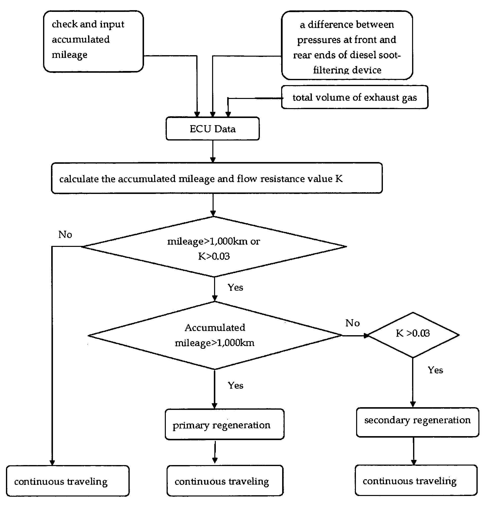
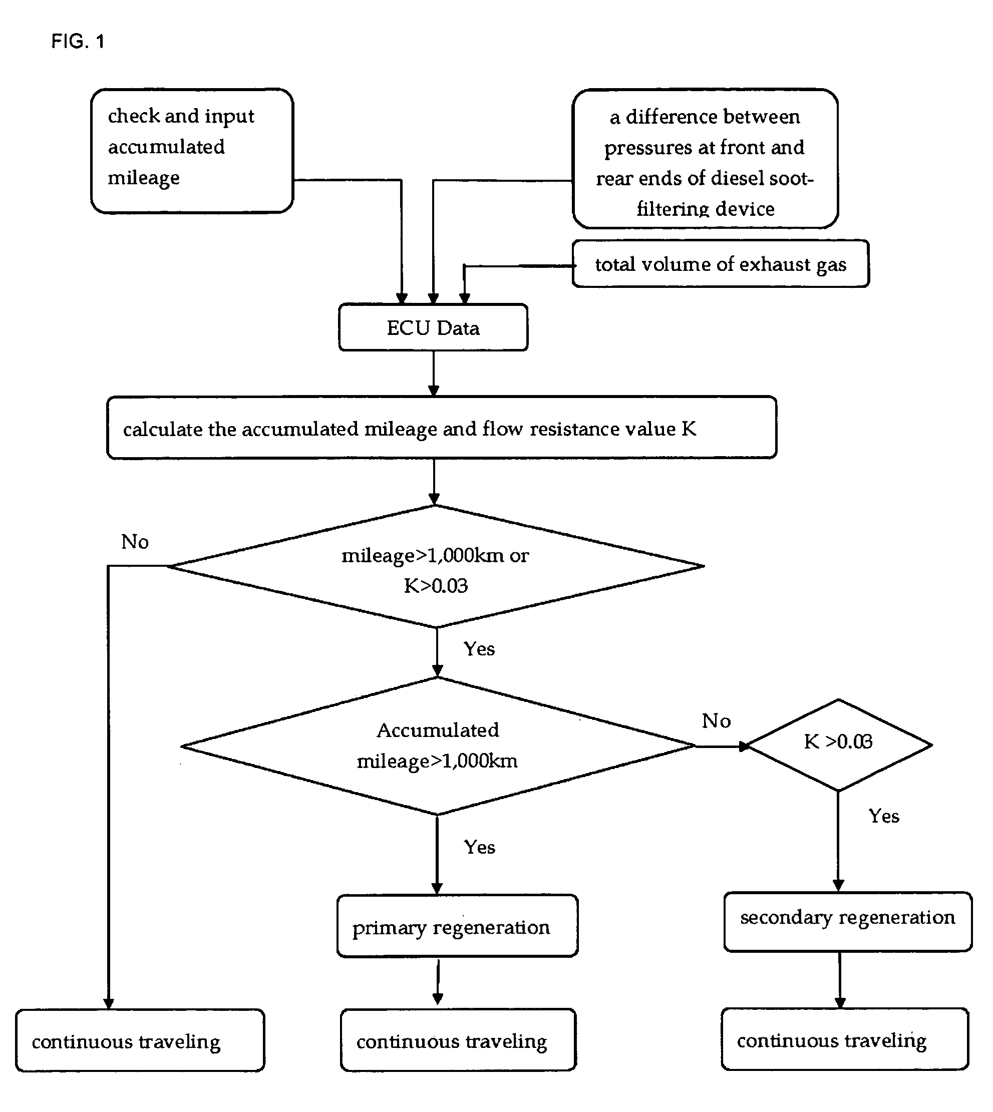
[0025] Embodiments of the present invention provide a method for regeneration of a diesel soot-filtering device, in which an appropriate regeneration logic is implemented by combining a degree of a natural regeneration and a degree of derived K value on a basis of the fact that it is difficult to protect CPF, i.e., a diesel soot-filtering device with only compulsory regeneration logic in consideration of a natural regeneration condition prior to the detection of a flow resistance value, i.e., a constant value K, thereby achieving a complete regeneration of the diesel soot-filtering device.

Problems solved by technology

However, the above-mentioned conditions are merely a regeneration condition for random experimentation, and do not take into consideration the operating conditions and variances arising from mass production of a vehicle.
The above condition generally cannot be applied to a specific diesel vehicle because such regeneration is only for prevention of error, but not as a result of identification of the start point and the conditions of regeneration.
Consequently, the regeneration logic according to the above-mentioned regeneration conditions never suggests a method of interrupting a decrease in fuel consumption ratio and an uncontrolled burning, which adversely affect the quality of the vehicle.
However, it is nearly impossible to carry out such a process since the weight of the soot-filtering device generally reaches 12 to 15 kg, and the soot weighs approximately 1 to 12 g which is in a relatively very small amount as compared to the weight of the device, resulting in a significant decrease in accuracy.
In addition, since the weight of the soot varies even in the case where foreign substances adhere to the outer appearance of the soot-filtering device while traveling, it is impossible to accurately measure the weight of the soot in real time.
If this constant value is not set, it is difficult to grasp the accumulated amount of the soot.
A disadvantage of the conventional prior art resides in the fact that since the accurate amount of soot accumulated in the diesel soot-filtering device is not determined, the accurate start point of regeneration of the accumulated soot within the diesel soot-filtering device is also not established.
As a result, the start point and the end point of regeneration of soot in the diesel soot-filtering device cannot be found, and there is little information regarding how much regeneration has been carried out.
Moreover, it is not possible to develop data on how the degree of regeneration is to be achieved.
However, it is generally not possible to recognize presently loaded data regarding the soot.
Although logic for the compulsory regeneration may be well designed, an uncontrolled burning may occur in a state where the logic is not used even once.
Also, during the compulsory regeneration, much burden may be imposed on the diesel soot-filtering device.

Method used


Image

  • Method for regeneration of diesel soot filtering device
  • Method for regeneration of diesel soot filtering device
  • Method for regeneration of diesel soot filtering device

Examples


Embodiment Construction

[0033] Reference will now be made in detail to the preferred embodiment of the present invention with reference to the attached drawings.

[0034] In view of the above-mentioned conditions, there is needed an improved method for determining the start and end points for the regeneration of a soot filtering device. Start and end points for regeneration may be determined by measuring a flow resistance value obtained by dividing a difference between pressures at front and rear ends of a diesel soot-filtering device by the flow rate of exhaust gas depending upon the amount of soot accumulated in a soot-filtering device regardless of the conditions of the engine and vehicle. This permits determination of a degree of accumulated soot and the measured corresponding flow resistance value, so that a software basis may be prepared. The start and end points of compulsory regeneration of the soot-filtering device can be easily determined through the later measurement of a flow resistance value in ...


PUM

PropertyMeasurementUnit
temperatureaaaaaaaaaa

Abstract

A method for regeneration of a diesel soot-filtering device includes the steps of inputting a flow resistance value that varies depending upon the amount of soot accumulated in the soot-filtering device; calculating the accumulated mileage and the flow resistance value (K); primarily compulsorily regenerating the diesel soot-filtering device if the mileage falls within a range from 200 to 10,000 km; and secondarily compulsorily regenerating the diesel soot-filtering device if the flow resistance value (K) falls within a range from 0.001 to 0.07.

Description

CROSS REFERENCE TO RELATED APPLICATIONS [0001] This application is based on, and claims priority from Korean Application No. 10-2004-0039431, filed on Jun. 1, 2004, the disclosure of which is hereby incorporated by reference. BACKGROUND OF THE INVENTION [0002] 1. Field of the Invention [0003] The present invention relates to a method for regeneration of a diesel soot-filtering device, and more particularly to such a device employing regeneration logic that considers both natural regeneration and compulsory regeneration of the device achieved by analyzing the degree of accumulated soot. [0004] 2. Background of the Related Art [0005] In the development of a diesel soot-filtering device, an important aspect of the control logic is the determination regarding the continue use of the soot filtering device. For this purpose, the soot accumulated within the diesel soot-filtering device should be continuously burned so as to prevent the diesel soot-filtering device from being blocked. Accor...

Claims


Application Information

Patent Timeline
Patent Type & Authority Applications(United States)
IPC IPC(8): B01D46/42F01N3/02F01N3/00F01N3/023F01N9/00
CPCF01N3/023Y02T10/47F01N9/002Y02T10/40F01N9/00
Inventor KIM, CHANG DAE
Owner HYUNDAI MOTOR CO LTD
Learn More