Plasma display device and driving method thereof

a technology of a display device and a driving method, which is applied in the direction of address electrodes, instruments, auxillary electrodes, etc., can solve the problems of delayed sustain discharge operation, and difficulty in achieving sustain discharge operation. , to achieve the effect of preventing faulty discharge, enhancing contrast, and performing an accurate address operation

Inactive Publication Date: 2005-12-01
SAMSUNG SDI CO LTD
View PDF4 Cites 5 Cited by
  • Summary
  • Abstract
  • Description
  • Claims
  • Application Information

AI Technical Summary

Benefits of technology

[0024] In accordance with the present invention an AWD driving method having the advantages of enhancing contrast and performing an accurate address operation, and a plasma display device and a driving method thereof having an advantage of preventing faulty discharge, have been provided.

Problems solved by technology

Therefore, such a DC PDP problematically requires a resistance for limiting the current.
Therefore, even if a specific pair of a first scan electrode and a first sustain electrode are addressed in the address period, a sustain discharge operation may not be immediately achieved, and the sustain discharge operation has to be delayed until every other pair of a scan and a sustain electrode are completely addressed.
Consequently, the address period is lengthened in each subfield such that a display period (i.e., a sustain discharge period) is relatively reduced, resulting in deterioration of brightness of light emitted from the PDP.
Therefore, according to such a conventional AWD driving method wherein the scan operation is performed only for the scan electrodes, accurate address operation becomes difficult since a width of the scan pulse is consequently narrowed.
In addition, the scan operation is not sufficiently performed, thereby limiting the number of possible subfields.
Therefore, a driving circuit for driving the Y electrode is different from that for driving the X electrode, and impedances of driving circuits for X and Y electrodes may not match each other.
In this case, discharge may become faulty since a waveform alternately applied to the X and Y electrodes may be distorted in the sustain discharge period.
In addition, according to a conventional AWD driving method, a waveform applied to the Y electrode is complex, and accordingly, an energy recovery circuit (ERC) used for the Y electrode also becomes complex.

Method used


Image

  • Plasma display device and driving method thereof
  • Plasma display device and driving method thereof
  • Plasma display device and driving method thereof

Examples


Embodiment Construction

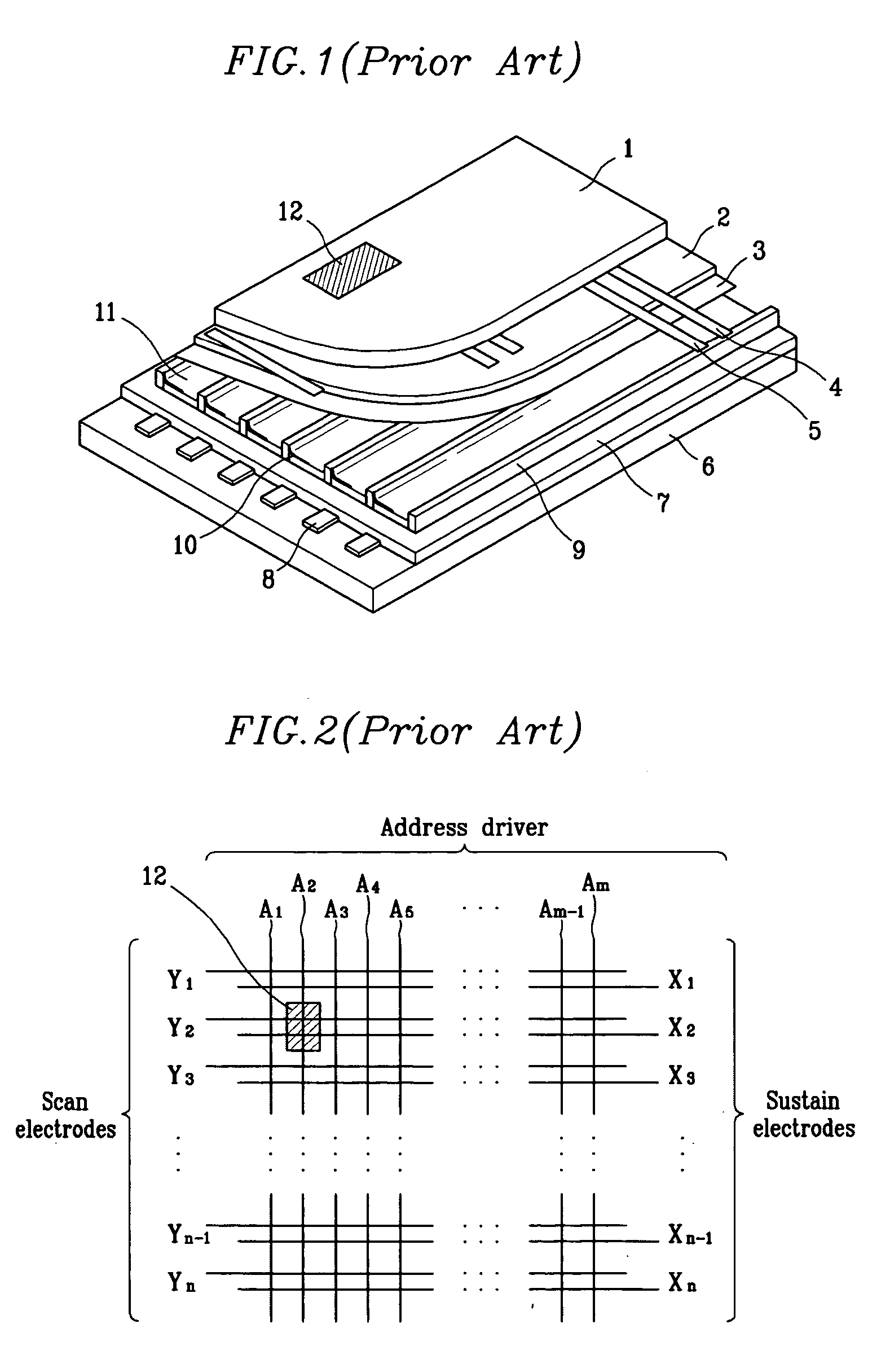
[0054]FIG. 6 is electrode arrangement diagram of a PDP according to an exemplary embodiment of the present invention. In the plasma display device a plurality of address electrodes A1-Am are arranged in parallel in a column direction. A plurality of Y electrodes Y1-Y(n+1) / 2, a plurality of X1-X(n+1) / 2, and a plurality of middle electrodes (M electrodes) M1-Mn are arranged in a row direction. That is, according to the embodiment of the present invention, respective M electrodes are arranged between Y and X electrodes, and the PDP has a four electrode structure wherein four electrodes of Y, X, M, and address electrodes (e.g., Y2, X2, M22, A2) contribute to forming of a discharge cell 30.

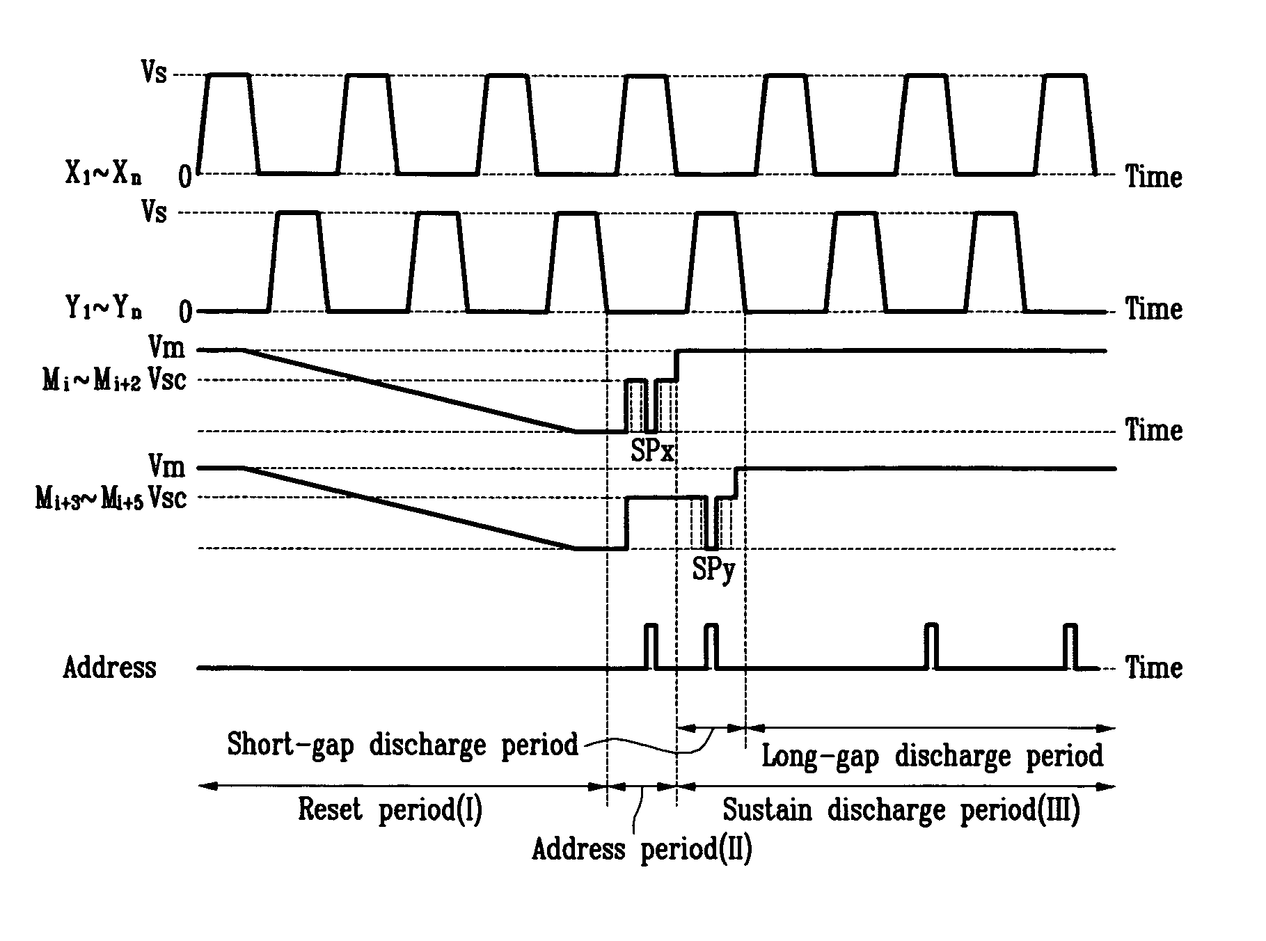
[0055] According to an exemplary embodiment of the present invention, the X and Y electrodes are electrodes for receiving a sustain pulse, and the M electrode is an electrode for receiving a reset waveform and a scan pulse.

[0056] Referring now to FIG. 7 and FIG. 8, a PDP according to an exemplary emb...


PUM


Abstract

A plasma display device and a driving method thereof. For a plasma display device having an M electrode between X and Y electrodes, a sustain pulse is applied to the X and Y electrodes during an entire period, and a reset waveform and a scan pulse are applied to the M electrode. In addition, a scan pulse is applied to the M electrode while applying the sustain pulse to the X or the Y electrode. As a result, a gently decreasing reset waveform may be used so as to enhance contrast. Furthermore, driving circuits for driving the X and Y electrodes may be designed with the same scheme. In addition, an accurate address operation may be achieved.

Description

CROSS-REFERENCES TO RELATED APPLICATIONS [0001] This application claims priority to and the benefit of Korean Patent Application Nos. 10-2004-0038926 and 10-2004-0038929 filed in the Korean Intellectual Property Office on the same day of May 31, 2004, the entire contents of which are incorporated herein by reference. BACKGROUND OF THE INVENTION [0002] 1. (a) Field of the Invention [0003] The present invention relates to a plasma display device and a driving method thereof. More particularly, the present invention relates to a plasma display device and a driving method thereof wherein the plasma display device is driven by an address-while-display (AWD) method. [0004] 2. (b) Description of the Related Art [0005] A plasma display device is a flat panel display that uses plasma generated by gas discharge to display characters or images. It includes a plasma display panel (PDP) and peripheral circuits. The PDP includes, depending on its size, more than several scores to millions of pixe...

Claims


Application Information

Patent Timeline
Patent Type & Authority Applications(United States)
IPC IPC(8): G09G3/20G09G3/288G09G3/291G09G3/292G09G3/294G09G3/296G09G3/298H01J11/12H01J11/22H01J11/24H01J11/26H01J11/28H01J11/32H01J11/34
CPCG09G3/2927G09G3/293G09G3/294G09G2320/0238G09G2310/0216G09G2310/0218G09G3/2986
Inventor YIM, SANG-HOON
Owner SAMSUNG SDI CO LTD
Why Eureka
Try Eureka