Autofocus system

a technology of autofocus and focus point, which is applied in the field of autofocus system, can solve the problems of high device cost, difficult to move an af point to the movement of the target subject, and complicated operation

Inactive Publication Date: 2005-12-01
FUJI PHOTO OPTICAL CO LTD
View PDF14 Cites 65 Cited by
  • Summary
  • Abstract
  • Description
  • Claims
  • Application Information

AI Technical Summary

Benefits of technology

[0022] According to the autofocus system of the present invention, an image signal of appropriate image quality can be obtained as an image signal for tracking for detection of the movement of a target subject on the screen. Furthermore, a change of a frame rate or an exposure adjustment can be made as necessary to obtain an image signal appropriate for tracking, and an AF area (AF frame) can be allowed to track a target subject without fail.
[0023] Additionally, although an image is changed relative to a desired target subject moving on the screen, the AF area (AF point) can track the target subject without fail, and a desired target can be continuously put into focus without a complicated operation of an operator in the AF.

Problems solved by technology

Therefore, the operation requires a complicated and careful job.
Especially, when a target subject moves quickly on the screen, there is the problem that it is difficult to move an AF point to the movement of the target subject.
However, in this system, there arises the following problem when an image signal of a subject image used for recording or regenerating is used as an image signal for tracking in the tracking device.
Therefore, a high performance circuit is used for each processing circuit of a tracking device, or a down-converting circuit is to be added, thereby causing a high cost required of the device.
In addition to the problem of cost, higher electric power is required in processing an image signal of high image quality than in processing an image signal of low image quality, and there is also the problem that high electric power is required in down-converting process on an image signal of high image quality.

Method used


Image

  • Autofocus system
  • Autofocus system
  • Autofocus system

Examples


Embodiment Construction

[0030] The autofocus system according to preferred embodiments of the present invention is described below in detail by referring to the attached drawings.

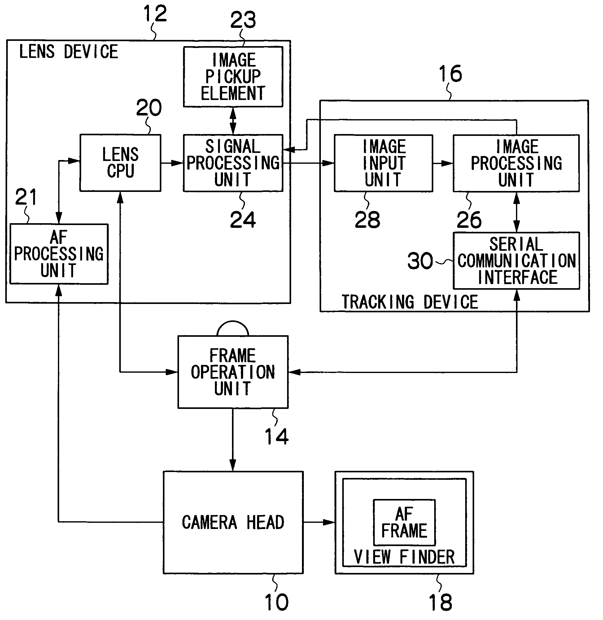
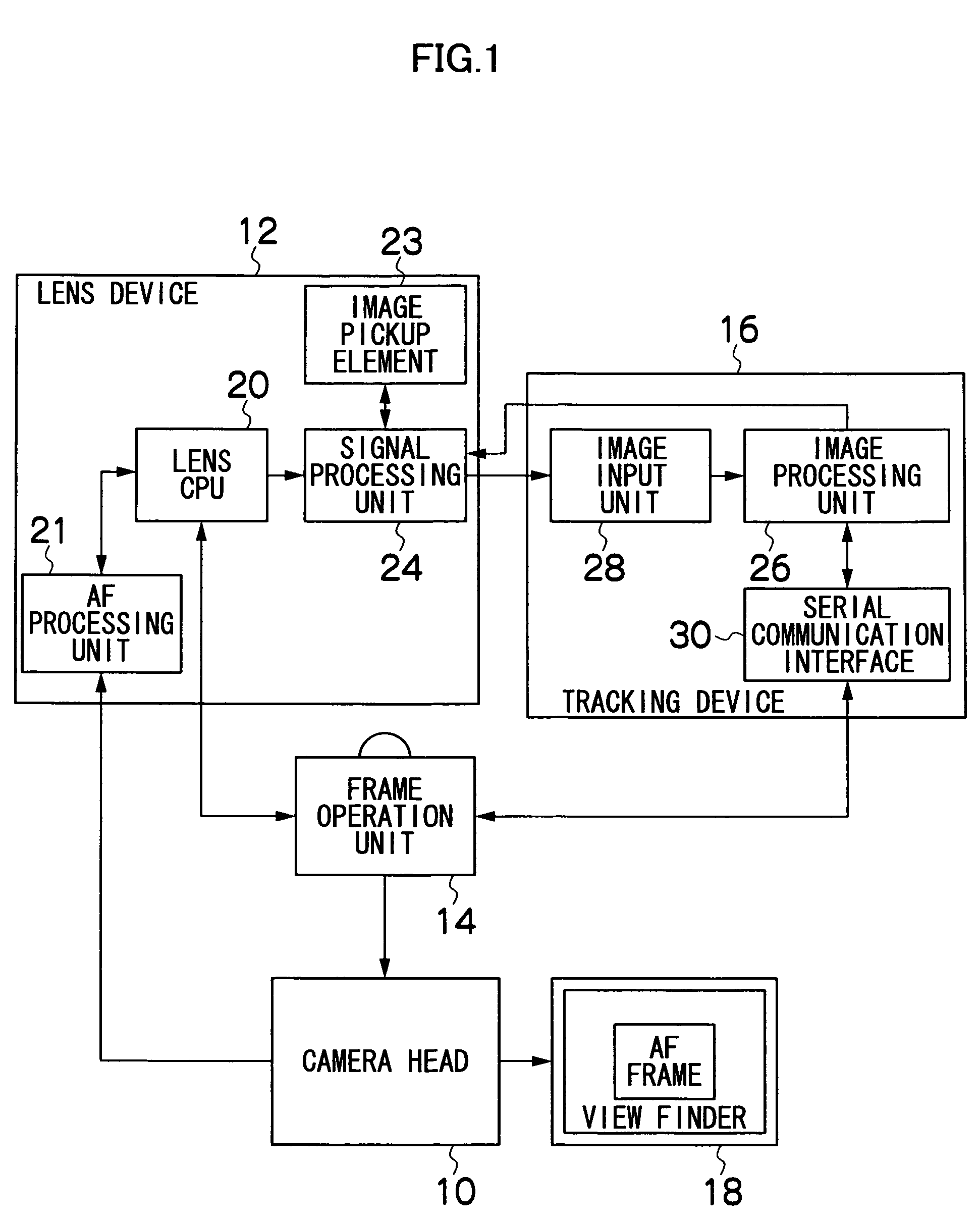
[0031]FIG. 1 is a block diagram showing the entire configuration of the image pickup system to which the autofocus system according to the present invention is applied. The image pickup system shown in FIG. 1 is, for example, an image pickup system used in shooting an image using a TV camera for a broadcast. FIG. 1 shows a camera head 10 whose lens can be switched, a lens device 12 having a taking lens (optical system) attached to the lens mount of the camera head 10, a frame operation unit 14, a tracking device 16, etc.

[0032] The camera head 10 is loaded with an image pickup element (for example, a CCD) not shown in the attached drawings, a predetermined signal processing circuit, etc., and the light from a subject entering the taking lens of the lens device 12 is formed on the image pickup surface of the image pickup element o...


PUM


Abstract

The autofocus system of the present invention is characterized by comprising a target subject specifying device which specifies a target subject to be put into focus, a tracking image pickup device which captures a subject image in the shooting range of the camera, and is provided in addition to an image pickup device of the camera which captures a subject image to be recorded or regenerated, a target subject movement detection device which detects a movement in the shooting range of the target subject specified by the target subject specifying device according to an image signal of a subject image captured by the tracking image pickup device, and an AF area change device which changes a range of the AF area such that the movement of the target subject detected by the target subject movement detection device is tracked.

Description

BACKGROUND OF THE INVENTION [0001] 1. Field of the Invention [0002] The present invention relates to an autofocus system, and more specifically to an autofocus system for automatically tracking a target subject in an AF area at a target range of autofocus (AF) in a shooting range of a camera. [0003] 2. Related Art [0004] With an image pickup system which converts an image of a subject to an electric signal (image signal) by an image pickup element (CCD, etc.) like a TV camera, a contrast system is generally used as an autofocus (AF) system. The contrast system is to detect the contrast of a subject image from an image signal fetched by an image pickup element, and control the focus of the taking lens such that the highest contrast can be obtained, thereby automatically obtaining focus in the best status. [0005] In the AF in the contrast system, the entire subject in the shooting range of a camera is not the target of the AF, but only a certain part of a subject in a part of range of...

Claims


Application Information

Patent Timeline
Patent Type & Authority Applications(United States)
IPC IPC(8): H04N5/232
CPCH04N5/23293H04N5/23212H04N23/675H04N23/61H04N23/635
Inventor SASAKI, TADASHIYATA, KUNIO
Owner FUJI PHOTO OPTICAL CO LTD
Why Eureka
Try Eureka