
Image sensing apparatus and an image sensing method

a technology of image sensing and image, applied in the field of image sensing apparatus, can solve problems such as poor contrast due to logarithmic compression

Active Publication Date: 2005-12-01
SONY SEMICON SOLUTIONS CORP
View PDF14 Cites 41 Cited by
  • Summary
  • Abstract
  • Description
  • Claims
  • Application Information

AI Technical Summary

Problems solved by technology

On the other hand, since an output natural-logarithmically converted in relation to an amount of an incident light can be obtained in the case of using the image sensor in a logarithmic operative state, there is an advantage of ensuring a wide dynamic range, whereas there is a disadvantage of a poorer contrast due to the logarithmic compression of an image signal.

Method used


Image

  • Image sensing apparatus and an image sensing method
  • Image sensing apparatus and an image sensing method
  • Image sensing apparatus and an image sensing method

Examples


Embodiment Construction

[0035] Hereinafter, one embodiment of the present invention is described with reference to the accompanying drawings.

(Description of the Outer Configuration of an Image Sensing Apparatus)

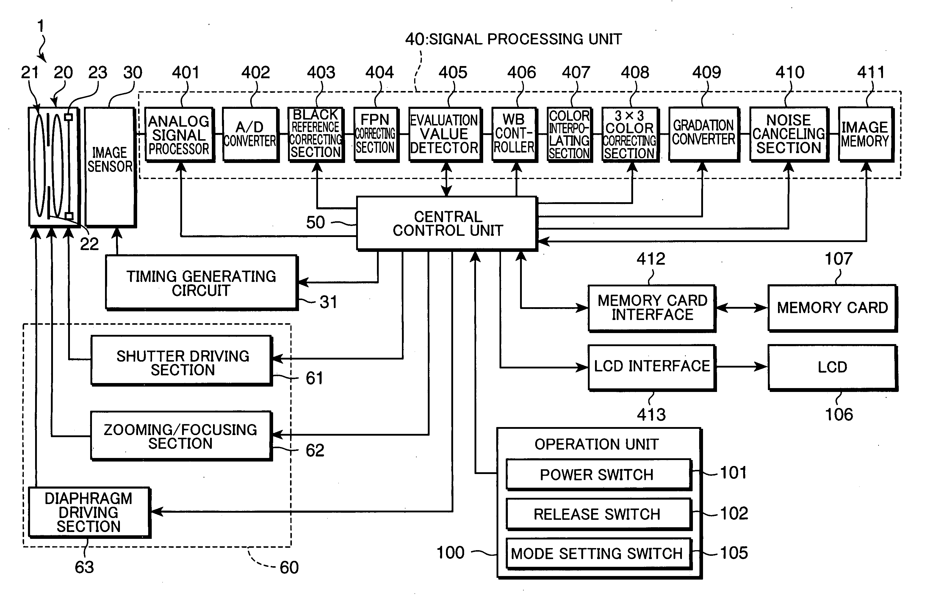
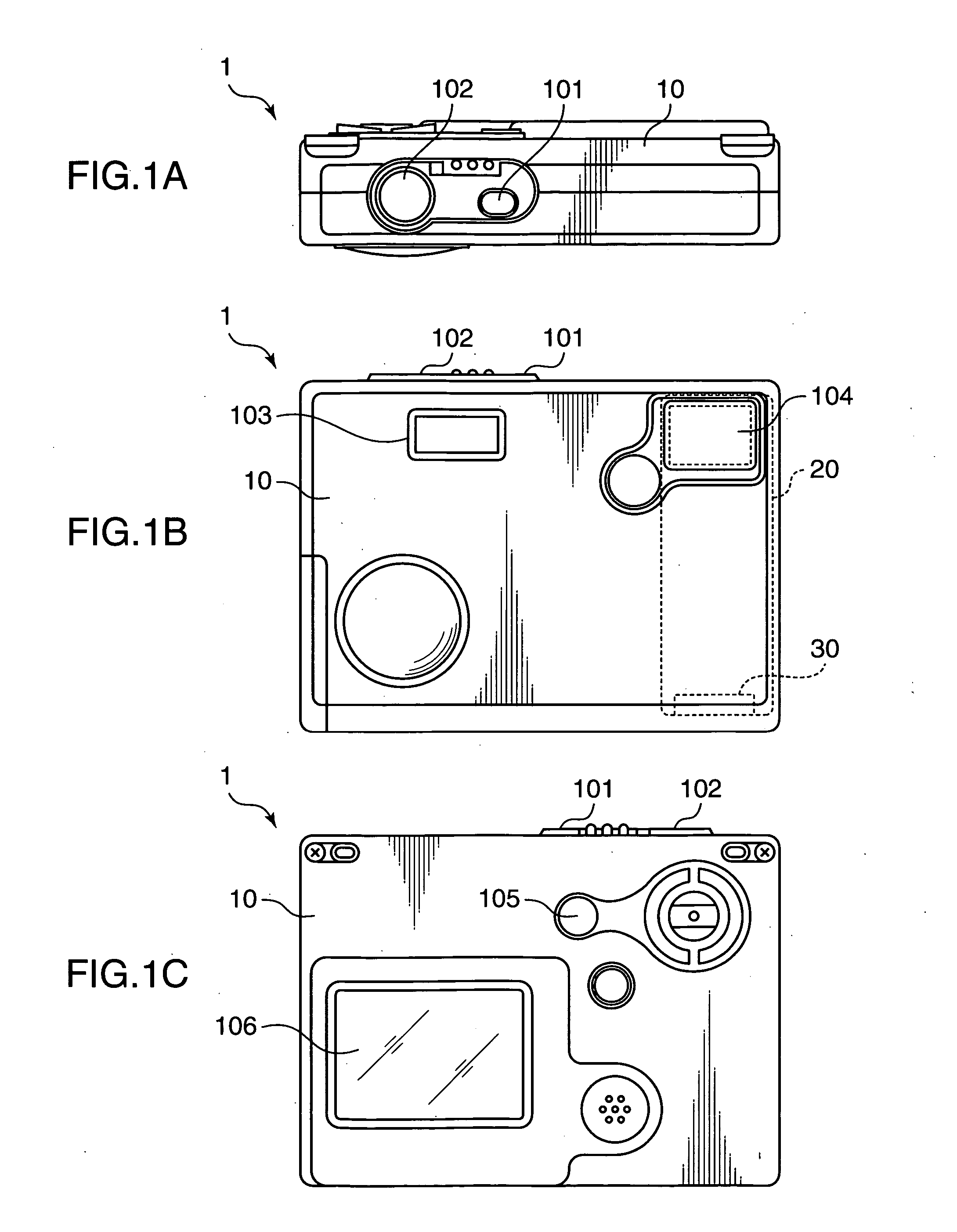
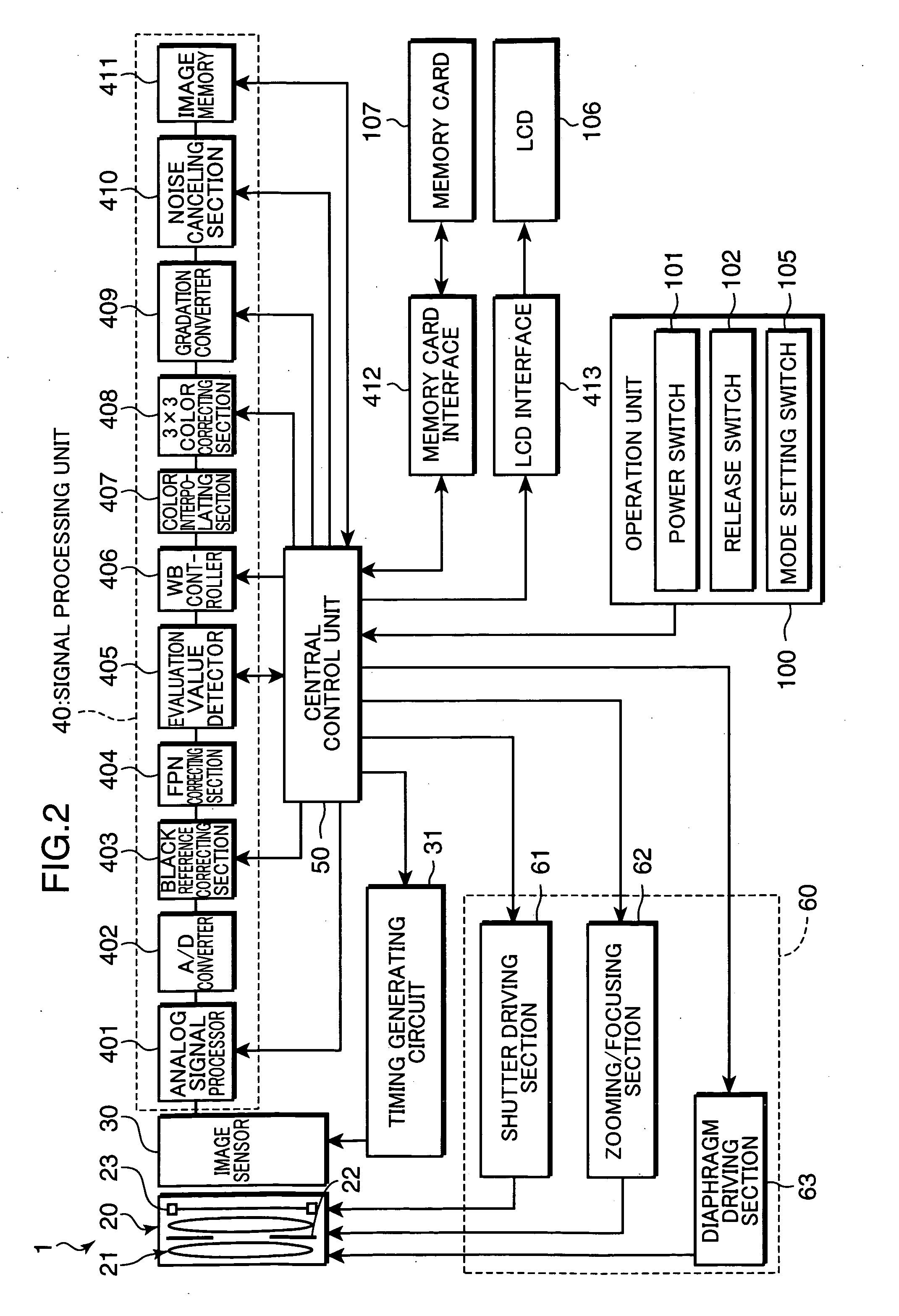
[0036]FIGS. 1A, 1B and 1C are a top view, a front view and a rear view showing the outer configuration of a small-size electronic camera 1 to which an image sensing apparatus according to the invention is suitably applied. On this electronic camera (image sensing apparatus) 1, a power switch 101, a release switch 102 and the like are arranged on the top surface of a camera main body 10; a flash firing section 103, a photographing lens window 104 and the like are arranged on the front surface; and various operation buttons such as a mode setting switch 105, a LCD device 106 including a liquid crystal monitor (LCD) and the like are arranged on the rear surface. In addition, a bent-type barrel 20 as well as various devices are arranged inside the main body 10.

[0037] The power switch 101 is a pressa...


PUM


Abstract

An image sensing apparatus is provided with an image sensor having a photoelectric conversion characteristic having a linear characteristic area where an electrical signal is outputted after being linearly converted in relation to an amount of an incident light and a logarithmic characteristic area where the electrical signal is outputted after being logarithmically converted in relation to the amount of the incident light; an evaluation value detector for detecting exposure evaluation values concerning an exposure control based on a luminance information of a subject; and a central control unit for controlling the exposure based on the exposure evaluation values detected by the evaluation value detector. The central control unit includes an exposure amount control parameter calculating section for controlling an exposure amount in accordance with the photoelectric conversion characteristic using the exposure evaluation values and a dynamic range control parameter calculating section for controlling a dynamic range in accordance with the photoelectric conversion characteristic using the exposure evaluation values. Accordingly, a subject image can be picked up while an optimal exposure is made for the subject and a specified dynamic range is attained.

Description

[0001] This application is based on Japanese patent application No. 2004-159760 filed on May 28, 2004, the contents of which are hereby incorporated by references. BACKGROUND OF THE INVENTION [0002] The present invention relates to an image sensing apparatus provided with an image sensor for generating an electrical signal corresponding to an amount of an incident light and particularly to an image sensing apparatus and an image sensing method using an image sensor having, as photoelectric conversion characteristics, a linear characteristic area where the electrical signal is linearly converted in relation to the amount of the incident light and a logarithmic characteristic area where the electrical signal is linearly converted in relation to the amount of the incident light (a linear characteristic operation and a logarithmic characteristic operation can be switched). [0003] There have been known image sensors (also called “LOG sensor”) in which a logarithmic converting circuit pro...

Claims


Application Information

Patent Timeline
Patent Type & Authority Applications(United States)
IPC IPC(8): G03B7/093H01L27/146H04N23/76H04N101/00
CPCH04N5/2351H04N5/243H04N5/2355H04N23/741H04N23/76H04N23/71
Inventor KAMON, KOICHISATO, KAZUCHIKAMINAKUTI, JUN
Owner SONY SEMICON SOLUTIONS CORP
Learn More