Color converting device, image forming apparatus, color conversion method, computer program and recording medium

a color conversion and image technology, applied in the field of color conversion devices, image forming apparatus, color conversion methods, computer program and recording media, can solve the problems of limiting the increase of the memory capacity of the color conversion table, large interpolation errors, etc., to minimize the lowering of color conversion accuracy, improve color conversion accuracy, and influence image quality

Active Publication Date: 2005-12-01
SHARP KK
View PDF6 Cites 38 Cited by
  • Summary
  • Abstract
  • Description
  • Claims
  • Application Information

AI Technical Summary

Benefits of technology

[0058] According to the present invention, it is possible to improve the color conversion accuracy by increasing the number of grid points of a color component which has great influence on image quality within a memory capacity limit of a lookup table or the like stored in the storage unit, and minimize the lowering of color conversion accuracy by decreasing the number of grid points of a color component which has little influence on image quality according to the memory capacity limit of the lookup table.
[0059] According to the present invention, the structure of a processing unit for calculating neighboring grid points of the color components of input image data is simple, and it is possible to achieve high-speed processing, low cost, and small size. Moreover, when the distance of the grid points is 2n (n is an integer smaller than the number of bits of each color component of input image data), since it is possible to calculate the grid points by bit shifting, the structure of the processing unit becomes simpler, and it is possible to further increase the speed and reduce the cost and the size.
[0060] According to the present invention, it is possible to perform color conversion using color correction values suitable for a type of an image based on input image data. For example, it is possible to perform color conversion using color correction values suitable for a type of a portion to be converted in an image based on input image data, and / or a type of a whole image. Further, it is possible to improve the color conversion accuracy within a limited memory capacity by setting the number of grid points for each type of an image based on input image data.

Problems solved by technology

However, since the three-dimensional interpolation method is often a linear interpolation method, if the relationship between input and output is non-linear, it suffers from a problem of large interpolation errors.
Moreover, if an attempt is made to increase the accuracy of color conversion, there arises a problem that the memory capacity of a LUT, etc. for storing the color conversion table increases.
Further, this method can limit the increase of the table size (memory capacity) compared with the method of improving accuracy by merely dividing all components finely.
However, in the method disclosed in Japanese Patent Application Laid Open No. 7-184073 (1995), since the grid widths are not uniform, it is necessary to perform a different division process according to a grid width, and the division process cannot be realized by only bit shifting.
Thus, there are problems that the circuit becomes larger in scale and complicated, and the processing speed becomes lower.
In addition, although some improvement of accuracy is expected by uneven grid widths, there is a problem that the number of grid points must be increased twice for a further improvement of accuracy.
Besides, the method disclosed in Japanese Patent No. 2874660 has the problem that it can only reduce the memory capacity which was increased by about 8 times when all components are divided twice finely to about 6 times. For example, it is only possible to reduce the increase of the memory capacity to about 6 times, 17×17×33×3=28611, from 17×17×17=4913.
Further, since there is data redundancy between a plurality of tables, there is a problem that the memory is not used effectively.

Method used


Image

  • Color converting device, image forming apparatus, color conversion method, computer program and recording medium
  • Color converting device, image forming apparatus, color conversion method, computer program and recording medium
  • Color converting device, image forming apparatus, color conversion method, computer program and recording medium

Examples


embodiment 1

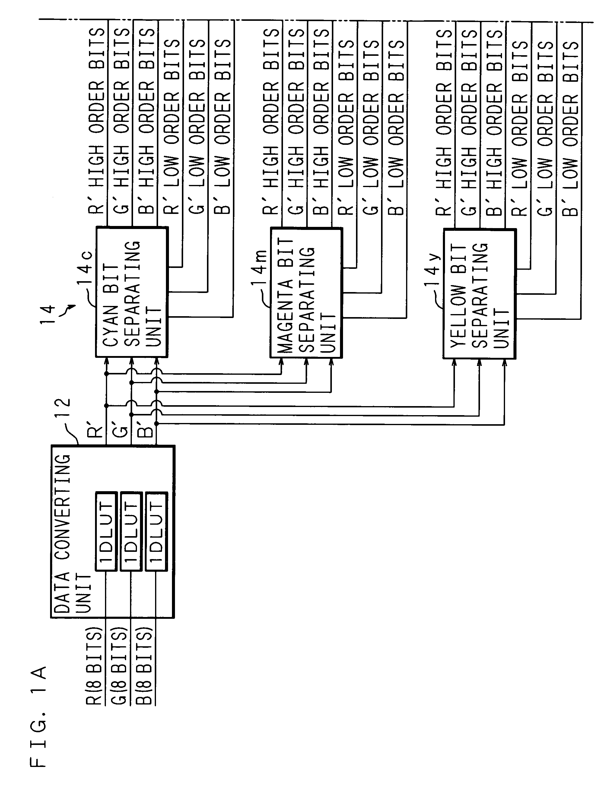
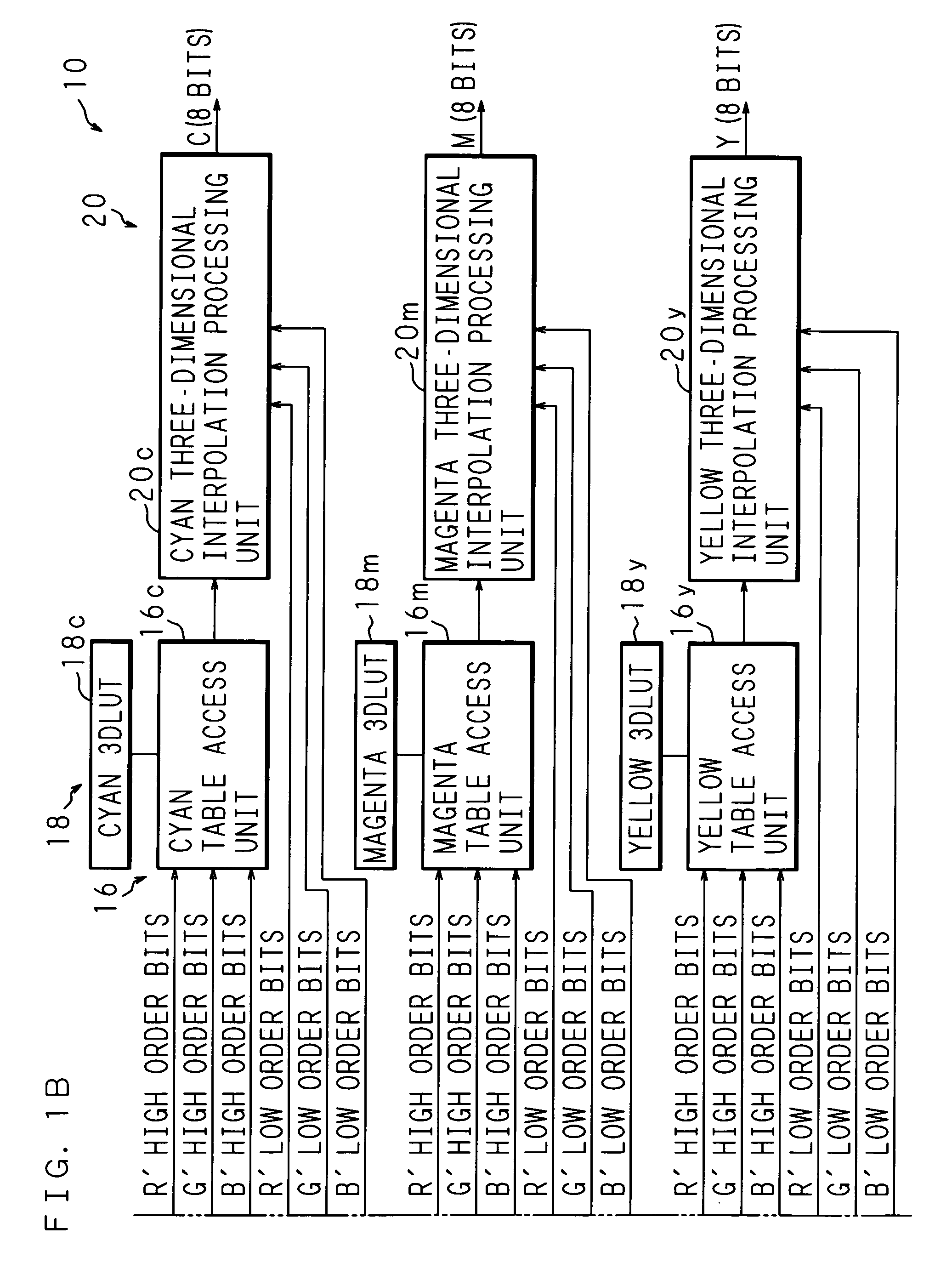
[0082]FIGS. 1A and 1B are block diagrams showing an example of a color converting device 10 of the present invention, and FIG. 1A continues on FIG. 1B. The color converting device 10 comprises a data converting unit 12 (a first data converting unit) into which image data represented by 8-bit R, G and B components is inputted; a bit separating unit 14 (a second data converting unit) into which later-described data is inputted from the data converting unit 12; a table access unit 16 (a second data converting unit) to which a three-dimensional lookup table (3DLUT) 18 is connected and later-described data is inputted from the bit separating unit 14; and a three-dimensional interpolation processing unit 20 (a second data converting unit) to which later-described data is inputted from the bit separating unit 14 and the table access unit 16, and which outputs image data represented by 8-bit C, M and Y components.

[0083] The bit separating unit 14 comprises a cyan bit separating unit 14c, a...

embodiment 2

[0099] It may also be possible to change the number of grid points to be increased or decreased, according to the types (cyan, magenta, and yellow) of the 3DLUTs 18. For example, it is possible to set the number of grid points as follows: [0100] cyan 3DLUT 18c: 20(R′)×18(G′)×18(B′), [0101] magenta 3DLUT 18m: 18(R′)×20(G′)×18(B′), and [0102] yellow 3DLUT 18y: 18(R′)×18(G′)×20(B′).

[0103] The complementary color of cyan is red, the complementary color of magenta is green, and the complementary color of yellow is blue. By increasing the number of grid points of a complementary color compared with the others, it is possible to perform highly accurate conversion.

[0104] In this case, however, it is necessary to provide a data converting unit 12 for each of cyan, magenta, and yellow. FIGS. 4A and 4B are block diagrams showing an example of the color converting device 10 comprising a cyan data converting unit 12c, a magenta data converting unit 12m and a yellow data converting unit 12y as ...

embodiment 3

[0106]FIG. 5 is a block diagram showing one example of the structure of an image forming apparatus 70 of the present invention. In this explanation, the image forming apparatus 70 acts as a digital color copying machine. The image forming apparatus 70 comprises a color image processing device 31, a color image input device 30, a color image output device 32 and an operating panel 33 connected to the color image processing device 31. Moreover, although not shown in FIG. 5, the image forming apparatus 70 comprises a CPU (Central Processing Unit) for controlling the respective devices in the image forming apparatus 70.

[0107] The color image input device 30 comprises a CCD (Charge Coupled Device), for example, reads an image of reflected light from a document by the CCD, and generates RGB analog signals. The generated RGB analog signals are sent to the color image processing device 31.

[0108] The color image processing device 31 comprises an AID (analog / digital) converting unit 311, a ...


PUM


Abstract

In a color converting device for converting input image data based on a plurality of first color components (the number of bits of each color component is k) into output image data based on plural of second color components by interpolation processing using a 3DLUT storing color correction values at grid points obtained by dividing a color space composed of the plurality of first color components, the distance of the grid points is 2n (where n is an integer smaller than k), the number Dn of grid points of the plurality of first color components is an integer satisfying 2m−1+1<Dn<2m+1+1 (where Dn≠2m+1, and m=k−n), and input image data is converted into output image data by converting each color component data of the input image data according to the number of grid points, and performing interpolation processing by reading color correction values corresponding to the converted color components from the 3DLUT.

Description

CROSS-REFERENCE TO RELATED APPLICATIONS [0001] This non-provisional application claims priority under 35 U.S.C. §119(a) on patent application No. 2004-160043 filed in Japan on May 28, 2004 and patent application No. 2005-49545 filed in Japan on Feb. 24, 2005, the entire contents of which are hereby incorporated by reference.BACKGROUND OF THE INVENTION [0002] 1. Field of the Invention [0003] The present invention relates to a color converting device and a color conversion method for converting input image data based on a plurality of first color components into output image data based on a plurality of second color components, an image forming apparatus comprising the color converting device, a computer program for causing a computer to convert input image data based on a plurality of first color components into output image data based on a plurality of second color components, and a recording medium storing the computer program. [0004] 2. Description of Related Art [0005] In recent ...

Claims


Application Information

Patent Timeline
Patent Type & Authority Applications(United States)
IPC IPC(8): H04N1/56H04N1/60
CPCH04N1/6019
Inventor GOTOH, MAKIOFURUICHI, GAKU
Owner SHARP KK
Why Eureka
Try Eureka