Unlock instant, AI-driven research and patent intelligence for your innovation.

Network receiving apparatus and network transmitting apparatus

Inactive Publication Date: 2005-12-01
KK TOSHIBA
View PDF3 Cites 3 Cited by
  • Summary
  • Abstract
  • Description
  • Claims
  • Application Information

AI Technical Summary

Benefits of technology

[0008] The present invention is made for solving such a problem, and an object thereof is to provide a network picture transmitting apparatus and a network picture receiving apparatus capable of preventing temporarily interruption in picture reproduction while reproducing streaming data transmitted at a variable bit rate.

Problems solved by technology

However, when a picture from a broadcast or an AV input is encoded by VBR (variable bit rate) for transmission / reception, reception of a constant amount of data takes long time at the time when data with a lower bit rate is being transferred, and an interval of transferring data to the decoder becomes long, so that an underflow of data occurs in the decoder and causes a problem such as interruption in displaying the picture.
However, in the case of the above-described prior art, the problem of network transmission inherent in ATMs is solved on the transmitting side, which is basically not effective for streaming data transmitted at a variable bit rate and thus causes a problem that a phenomenon of temporary interruption in picture reproduction occurs on the receiver side when there is a significant change in the bit rate.

Method used


Image

  • Network receiving apparatus and network transmitting apparatus
  • Network receiving apparatus and network transmitting apparatus
  • Network receiving apparatus and network transmitting apparatus

Examples


first embodiment

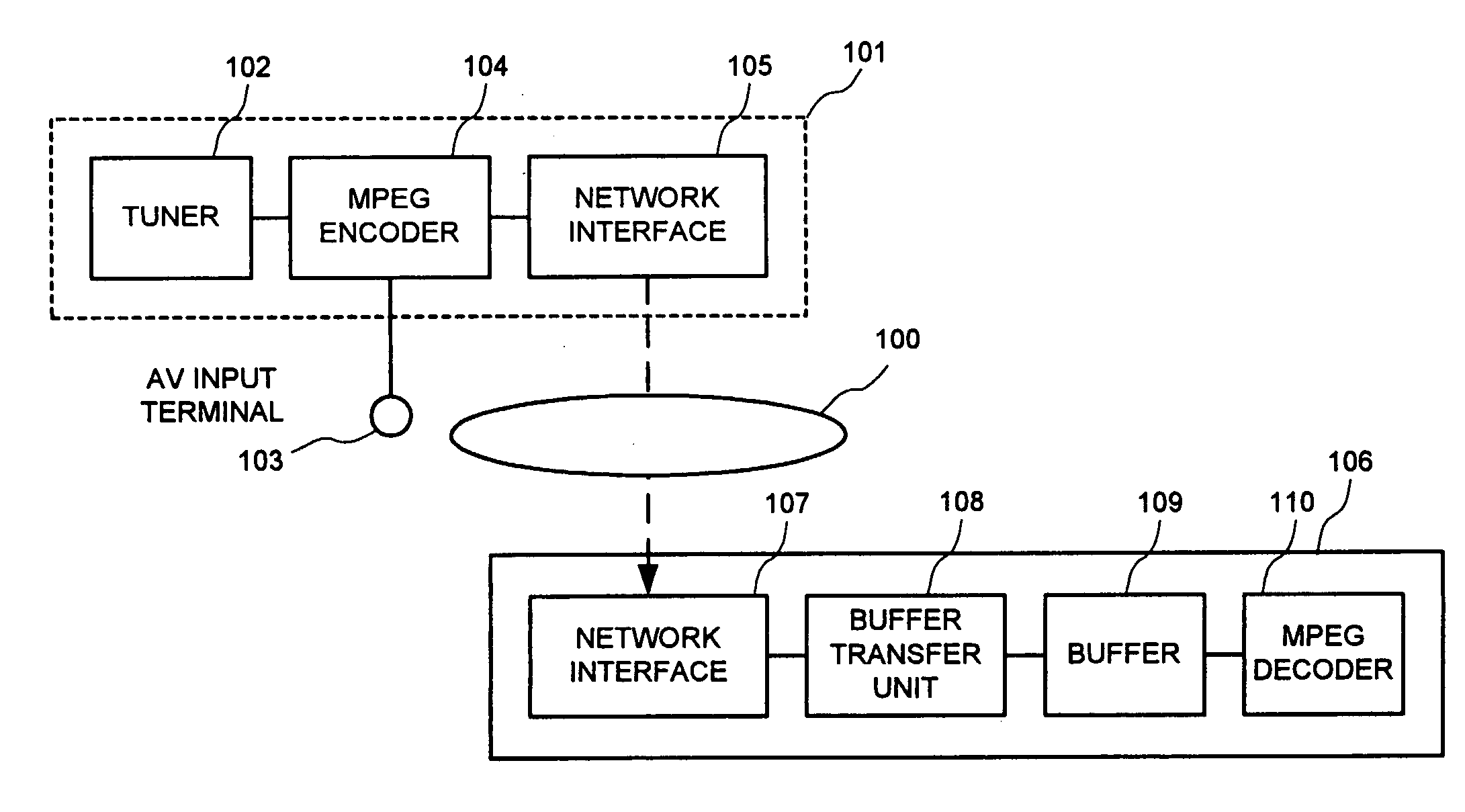
[0067] Thus, according to the network picture transmitting and receiving system of this first embodiment, the buffer transfer unit 108 performs transfer of data to the buffer 109 by a unit of constant reproduction time, a unit of constant number of GOP, or a unit of constant number of frames, so that the data is transferred at a constant time interval from the buffer 109 to the MPEG decoder 110.

[0068] A network picture transmitting and receiving system of a second embodiment according to the present invention will be described with reference to FIG. 8. Note that the same components as those in the above-described first embodiment will be designated the same reference numerals, and the description thereof will be omitted.

second embodiment

[0069] As shown in FIG. 8, a network picture transmitting apparatus 101 of the network picture transmitting and receiving system of this second embodiment has a tuner 102, an MPEG encoder 104 having an AV (audiovisual) input terminal 103, a transfer control unit 111, a network interface 105 (referred to as network I / F 105 below), and so on, and transmits an MPEG picture stream via a network 100 such as a wireless LAN, wired LAN, or the like for example to a network picture receiving apparatus 106.

[0070] The MPEG encoder 104 performs MPEG encoding of a broadcast signal received by the tuner 102 or a picture signal inputted from the AV input terminal 103 and transfers this to the transfer control unit 111.

[0071] The transfer control unit 111 transfers the data transferred from the MPEG encoder 104 to the network I / F 105 by a unit of constant display time, a unit of constant number of GOP, or a unit of constant number of frames. The network I / F 105 transmits an MPEG picture stream to ...


PUM


Abstract

A network picture receiving apparatus is a network picture receiving apparatus that is connected to a network 100 and includes: a network I / F 107 as a receiving unit configured to receive an MPEG picture stream from the network 100; a buffer 109 having a predetermined capacity and configured to perform buffering of the MPEG picture stream; a buffer transfer unit 108 configured to transfer the MPEG picture stream received by the network I / F 107 to the buffer 109 by a unit of predetermined reproduction time obtained from the MPEG picture stream; and an MPEG decoder 110 configured to decode the MPEG picture stream buffered in the buffer 109 into an original picture signal.

Description

CROSS-REFERENCE TO THE INVENTION [0001] This application is based upon and claims the benefit of priority from the prior Japanese Patent Application No. 2004-157649, filed on May 27, 2004; the entire contents of which are incorporated herein by reference. BACKGROUND OF THE INVENTION [0002] 1. Field of the Invention [0003] The present invention relates to a network transmitting apparatus which transmits, for example, an MPEG picture stream, and a network receiving apparatus which receives such an MPEG picture stream. [0004] 2. Description of the Related Art [0005] Conventionally, in an apparatus which transmits and receives a picture via a network, a receiving device transfers received data to a decoder by a unit of constant amount. However, when a picture from a broadcast or an AV input is encoded by VBR (variable bit rate) for transmission / reception, reception of a constant amount of data takes long time at the time when data with a lower bit rate is being transferred, and an inter...

Claims


Application Information

Patent Timeline
IPC IPC(8): H04N7/24H04N19/00H04N19/70H04N21/234H04N21/44
CPCH04L47/10H04N21/44004H04N21/23406H04L47/22
Inventor MAEDA, SHIGERU
Owner KK TOSHIBA