

Image providing method and device
a technology of providing method and providing device, applied in the field of providing method and device, can solve problems such as poor interactivity
- Summary
- Abstract
- Description
- Claims
- Application Information
AI Technical Summary
Problems solved by technology
Method used
Image

Examples
first embodiment
The First Embodiment
[0033]FIG. 4 shows a configuration of an interactive type image display system according to the first embodiment of the present invention. This system includes: image providing device 1 for transforming a fish-eye image to a dewarped image in a designated visual-field; fish-eye imaging device 2 for providing in real-time an all-direction image, particularly a moving image, to the image providing device 1; digital-image file storage unit 3 for accumulating a fish-eye image that is previously imaged by the fish-eye imaging device and the like in a form of a digital-image file such as MPEG 2 file and JPEG file group and the like; input device 4 for inputting, as an external control, information such as the user-desired sight-line direction (theta, phi) and zoom magnification (field angle gamma); and output device 5 such as a monitor for displaying the dewarped image dewarped by image providing device 1.
[0034] Image providing device 1 includes mainly input processin...
second embodiment
The Second Embodiment
[0046] The processing of dewarping computing module 22 can be performed even more quickly using the graphics function such as a graphics dedicated processor (GPU). Specifically, significant processing can be performed on the graphics-board side by considering plane A indicating the drawing area in FIG. 1 as the object of the texture mapping performed in three-dimension.
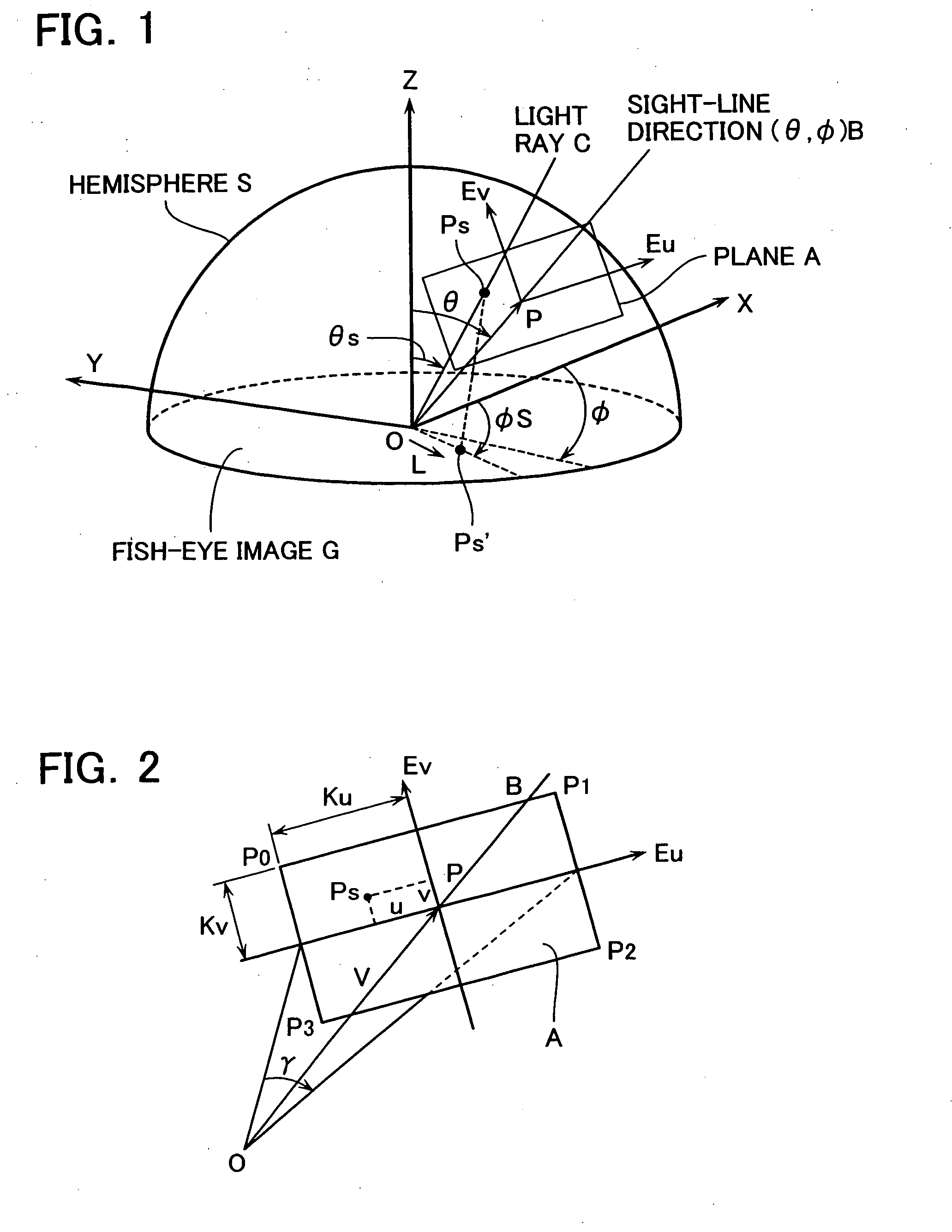
[0047]FIG. 8 shows the dewarping processing using the graphics function. The processing falls into application software and graphics processing. The application software calculates the three-dimensional position of each point at four corners in the drawing area (P0, P1, P2, and P3 in FIG. 2) (S21). The three-dimensional texture mapping and indent processing of the graphics processing on the graphics-board side performs the computation of each pixel position in the drawing area (S22) and non-linear texture mapping processing (S23). The interpolation processing from the three-dimensional positions ...
third embodiment
The Third Embodiment
[0052] When the drawing area is previously established, and the processing is limited to this drawing area, only a portion of the original fish-eye image G will be processed. Management function unit 21 in FIG. 4 thus cuts out a portion of the original fish-eye image G for the processing.
[0053] Suppose that, for example, fish-eye image G divides into a plurality of blocks g and the decoding processing occurs for each block, as in FIG. 9. In the embodiments of the present invention, it is supposed that Ku and Kv shown in Equation 1 and three-dimensional positions at four corners shown in Equation 7 are determined. The embodiment then uses such information to calculate the coordinate values of eight points P1 to P8 around the area to be processed, and incorporates only blocks g (hatched blocks in FIG. 9) containing these coordinate values as the blocks to be processed in input processing unit 11. This is possible in MPEG 2 and JPEG and the like, for example, by sp...
PUM
 Abstract
Description
Claims
Application Information