Structure of demister hose for vehicles

a demister hose and vehicle technology, applied in vehicle heating/cooling devices, transportation and packaging, foundation engineering, etc., can solve the problems of deterioration in operational efficiency, disadvantageous sight, defrosting of vehicle door windows, etc., to improve aesthetic value and quality of products, improve defrosting efficiency

Active Publication Date: 2005-12-01
HYUNDAI MOBIS CO LTD
View PDF1 Cites 1 Cited by
  • Summary
  • Abstract
  • Description
  • Claims
  • Application Information

AI Technical Summary

Benefits of technology

[0018] With such a configuration as stated above, it is possible to prevent defrost air from leaking from a gap between the demister hose and a demister outlet, thereby improving defrosting efficiency. Further, it is possible to prevent a seal pad from protruding toward the interior of the demister hose upon being compressed, and thus to eliminate the need for any operation for hiding the seal pad so as not to be seen from the outside, resulting in improvement in the aesthetic value and quality of products, as well as in operational efficiency.

Problems solved by technology

In this case, part of the blown defrost air flows through a demister hose connected to the defroster duct and is discharged from a demister outlet, resulting in defrosting a vehicle's door windows.
The problem with the above described conventional structure is that the demister hose 40 excessively compresses the seal pad 30 when it is fitted around the demister outlet 20, thereby causing the seal pad 30 to protrude toward the interior of the demister hose 40, and thus be disadvantageously seen from the outside through the demister outlet 20.
Such an exposure of the seal pad 30 requires somewhat troublesome manual operation for removing or hiding the seal pad 30 so as not to be seen from the outside, resulting in deterioration in operational efficiency.

Method used


Image

  • Structure of demister hose for vehicles
  • Structure of demister hose for vehicles
  • Structure of demister hose for vehicles

Examples


Embodiment Construction

[0023] Now, a preferred embodiment of the invention will be explained with reference to the accompanying drawings.

[0024] Further, the present embodiment is given by way of illustration and example only, and is not intended to limit the range of the present invention. Multiple variations and modifications are possible through the technical teachings of the present invention.

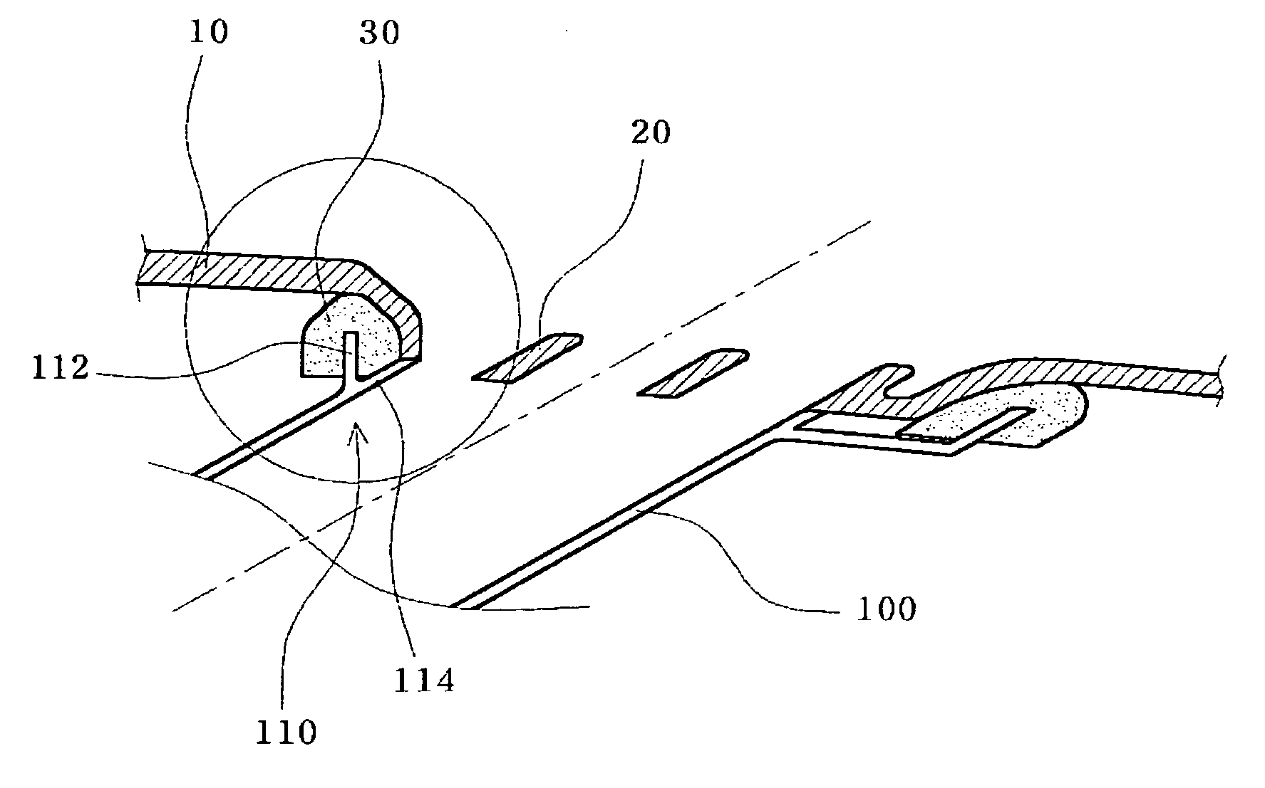
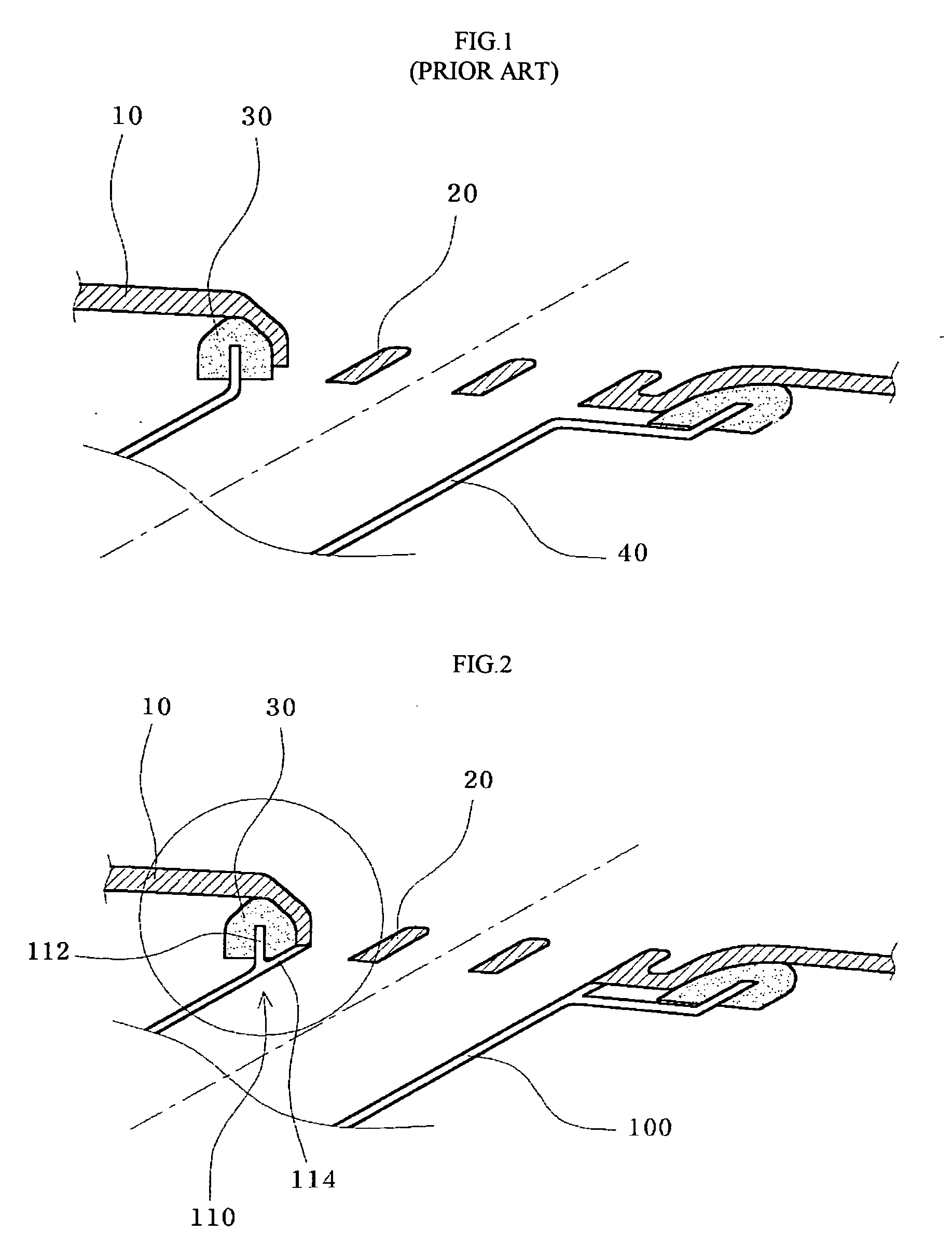
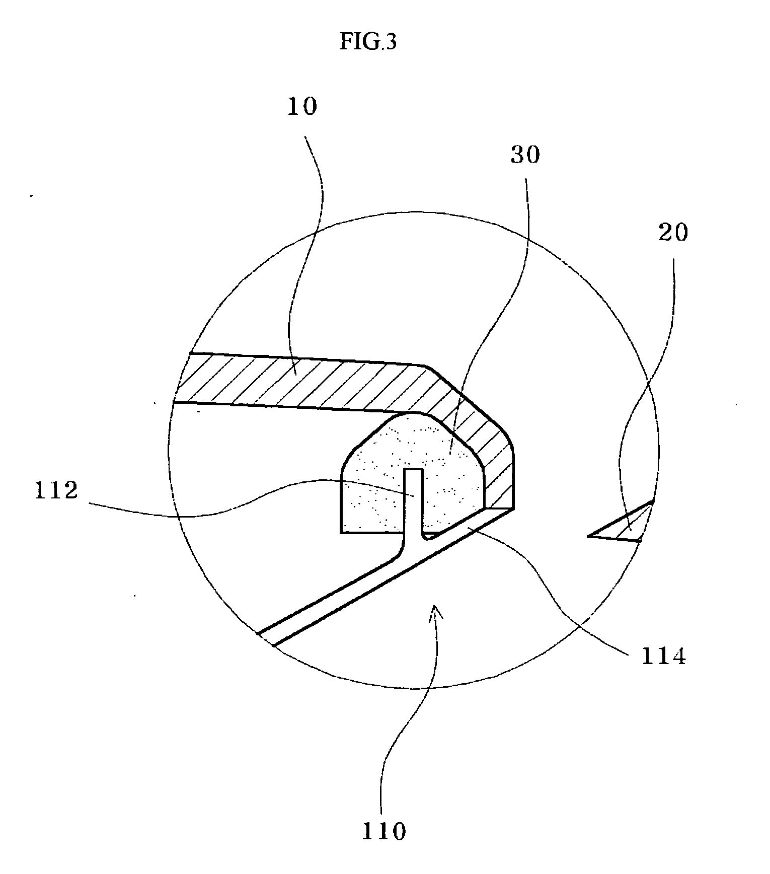
[0025]FIG. 2 is a schematic view illustrating the structure of a demister hose for vehicles in accordance with the present invention. FIG. 3 is an enlarged view illustrating an important portion of the structure of the demister hose in accordance with the present invention.

[0026] As shown in FIGS. 2 and 3, at one lateral side of the vehicle crash pad 10 is formed the demister outlet 20, and a demister hose of the present invention, which is designated as reference numeral 100, is located at the lower side of the demister outlet 20. Between the demister hose 100 and the demister outlet 20 is provided a seal pad ...


PUM


Abstract

A structure of a demister hose for vehicles includes a demister outlet formed in a crash pad, a seal pad provided along an outer circumferential edge of the demister outlet and a restraint that guides defrost air toward the demister outlet and that prevents the seal pad from protruding toward the interior of the demister hose.

Description

RELATED APPLICATIONS [0001] The present disclosure relates to subject matter contained in Korean Application No. 10-2004-34793, filed on May 17, 2004, which is herein expressly incorporated by reference in its entirety. BACKGROUND OF THE INVENTION [0002] 1. Field of the Invention [0003] The present invention relates in general to a demister hose, and more particularly to the structure of a demister hose for vehicles, wherein one end of the demister hose is divided along the circumference thereof into outer and inner branches so that the outer branch corresponds to a seal pad, and the inner branch corresponds to a demister outlet, thereby preventing the seal pad from protruding toward the interior of the demister hose upon being compressed, and thus eliminating the need for any operation for hiding the seal pad so as not to be seen from the outside, resulting in improvement in the aesthetic value and quality of products, as well as operational efficiency. [0004] 2. Description of the...

Claims


Application Information

Patent Timeline
Patent Type & Authority Applications(United States)
IPC IPC(8): B62D25/08B60H1/00B60H1/34
CPCB60H2001/00635B60H1/3407E02B3/14E02D5/76E02D29/0266E02D2600/20E02D2600/30
Inventor KA, SUK-SUN
Owner HYUNDAI MOBIS CO LTD
Why Eureka
Try Eureka