Non-contact method and system for tire analysis

a non-contact, tire technology, applied in vehicle tyre testing, vehicles, instruments, etc., can solve problems such as uneven wear of tires, and achieve the effect of convenient observation

Active Publication Date: 2005-12-08
SNAP ON INC
View PDF15 Cites 67 Cited by
  • Summary
  • Abstract
  • Description
  • Claims
  • Application Information

AI Technical Summary

Benefits of technology

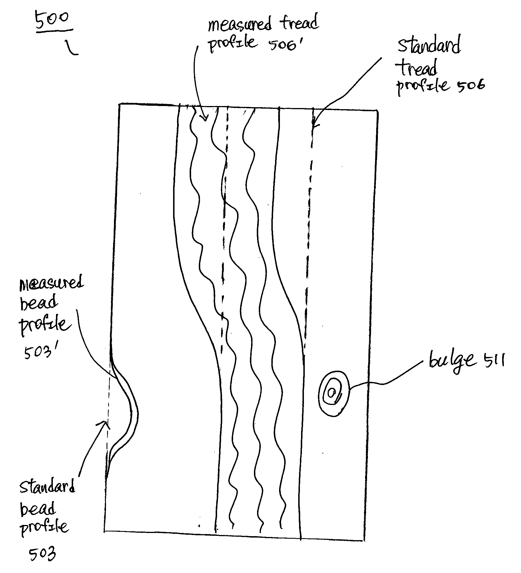
[0011] The condition of the tire may be determined by generating a surface profile showing respective heights or depths on the surface of the tire. For example, the surface of the tire can be scanned by rotating the wheel assembly to which the tire is attached for 360 degrees. During the rotation, the emitter source continuously emits radiations onto the wheel assembly, and the detector continuously obtains signals reflected from

Problems solved by technology

If a significant difference exists, it is

Method used


Image

  • Non-contact method and system for tire analysis
  • Non-contact method and system for tire analysis
  • Non-contact method and system for tire analysis

Examples


Embodiment Construction

[0027] In the following description, for the purposes of explanation, numerous specific details are set forth in order to provide a thorough understanding of the present disclosure. It will be apparent, however, to one skilled in the art that the present method and system may be practiced without these specific details. In other instances, well-known structures and devices are shown in block diagram form in order to avoid unnecessarily obscuring the present disclosure.

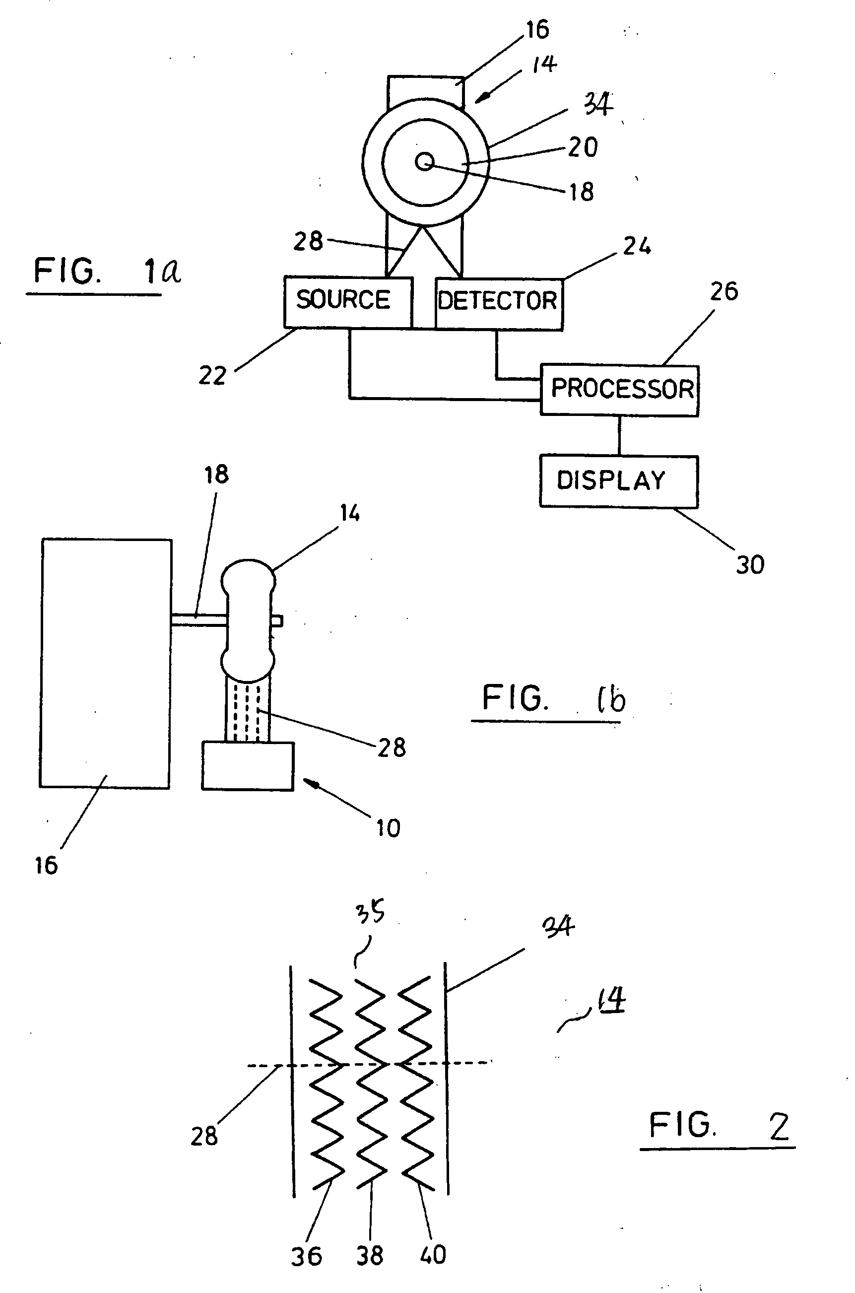
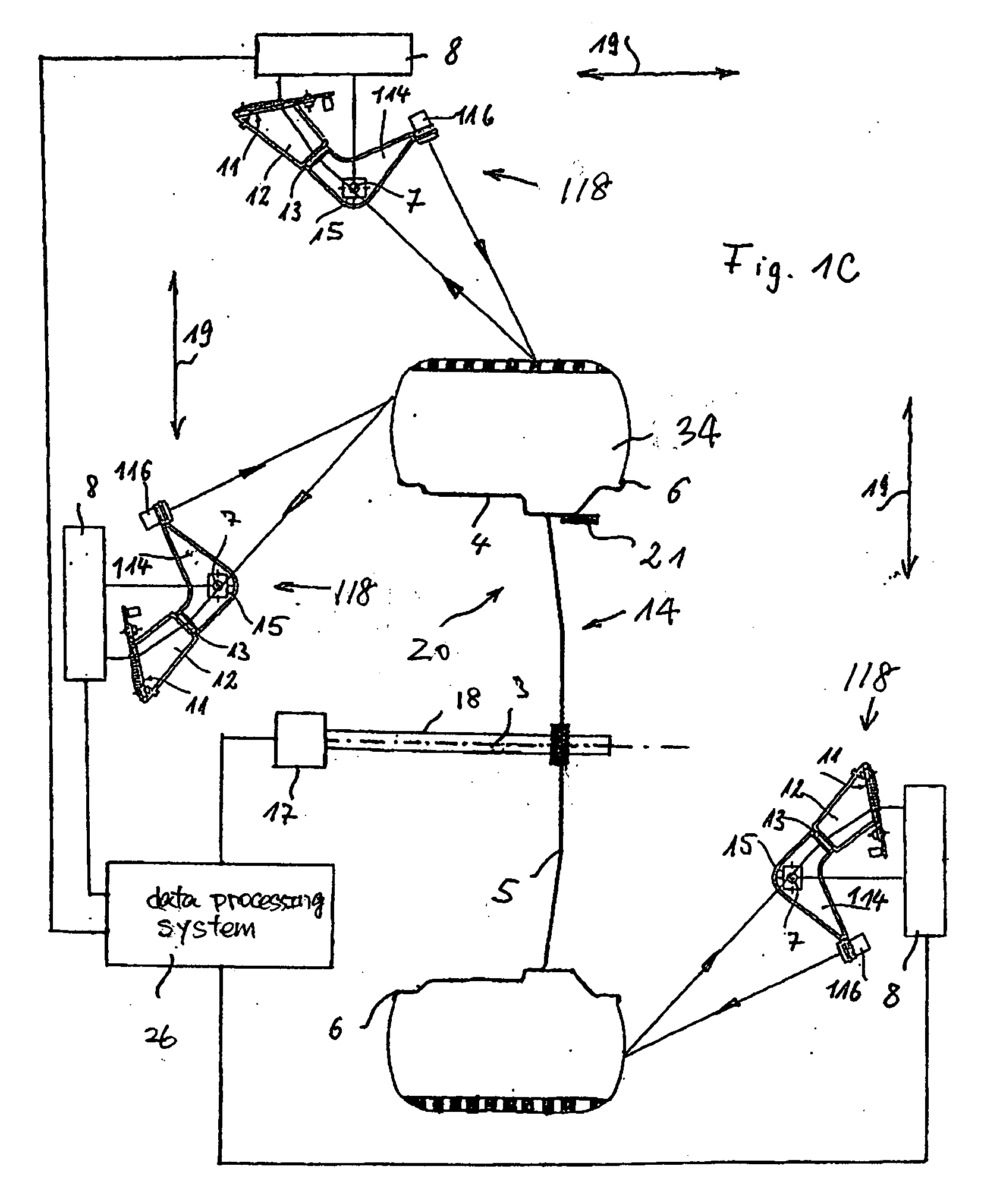
[0028]FIGS. 1a and 1b show an exemplary non-contact analytical system 10 for determining the condition of a tire 34 or wheel assembly 14 by analyzing a profile of the tire 34 or wheel assembly 14 that includes geometrical information, such as height and / or depth, related to various points of the tire 34 or wheel assembly 14. Examples of various types of non-contact measurement devices are discussed in U.S. Pat. No. 6,535,281, titled “METHOD AND APPARATUS FOR OPTICALLY SCANNING A VEHICLE WHEEL,” and U.S. Pat. No. 6,069...


PUM


Abstract

A non-contact method and system for analyzing tire conditions. The system includes an emitter source for emitting radiation signals towards a tire having a treaded surface between two sidewalls. A detector is provided to receive signals reflected by the tire in response to the emitted radiation signals. A data processing system, coupled to the emitter source and the detector, obtains geometrical information, such as height, of a plurality points on the tire based on the signals received from the detector. The data processing system determines a condition of the tire by comparing geometrical information for a designated portion of the plurality points with other portion points on the tire. A color-coded surface profile showing a height distribution of the tire is also generated to assist diagnosis of the tire.

Description

FIELD OF DISCLOSURE [0001] This disclosure generally relates to vehicle service systems utilizing non-contact data collection and analysis, and more specifically, to applying unique analytical methods to data obtained by non-contact measurement systems in order to determine conditions of tires or wheel assemblies by creation and analysis of a profile of the tire or wheel assembly. BACKGROUND AND SUMMARY OF THE DISCLOSURE [0002] The following terms may be used throughout the descriptions presented herein and should generally be given the following meanings unless contradicted or elaborated upon by other descriptions set forth herein. [0003]“Wheel” refers to a generally cylindrical, typically metallic, disc-like mechanical support for supporting a typically pneumatic tire and mounting to a vehicle axle. A wheel has two axially spaced-apart flanges (or annular lips), each flange adapted to securely receive a respective one of the two beads of the mounted tire. [0004]“Tire” is a laminat...

Claims


Application Information

Patent Timeline
IPC IPC(8): G01B11/22G01M17/02
CPCG01M17/027G01B11/22
Inventor DALE, JAMES L. JR.ZHOU, WEN YUROGERS, FREDERICK J.
Owner SNAP ON INC
Why Eureka
Try Eureka