Tire with rotation period indication hole, and method of indicating tire rotation period

a technology of tire rotation and indication hole, which is applied in the field of vehicle tires, can solve the problems of missing a suitable rotation timing, and achieve the effects of long time use, accurate indication of the rotation period, and convenient recognition

Inactive Publication Date: 2005-12-08
SUMITOMO RUBBER IND LTD
View PDF22 Cites 18 Cited by
  • Summary
  • Abstract
  • Description
  • Claims
  • Application Information

AI Technical Summary

Benefits of technology

[0021] Since the tire rotation timing is indicated by a change of the contour of the rotation timing indication hole, for example, from a shape with curved lines to a shape with straight lines, the tire rotation timing can be extremely easily recognized by a visual check as compared to the conventional technology wi...

Problems solved by technology

However, in these conventional technologies, since the contour of the rotation timing indication hole is formed in either a circ...

Method used


Image

  • Tire with rotation period indication hole, and method of indicating tire rotation period
  • Tire with rotation period indication hole, and method of indicating tire rotation period
  • Tire with rotation period indication hole, and method of indicating tire rotation period

Examples


Embodiment Construction

[0027] The embodiments of the invention will be described below on the basis of the drawings.

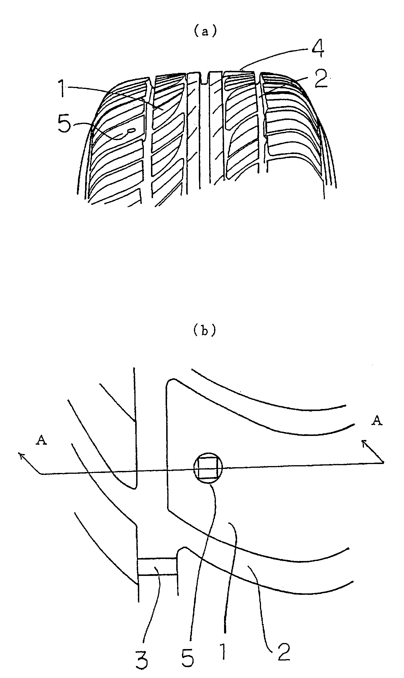
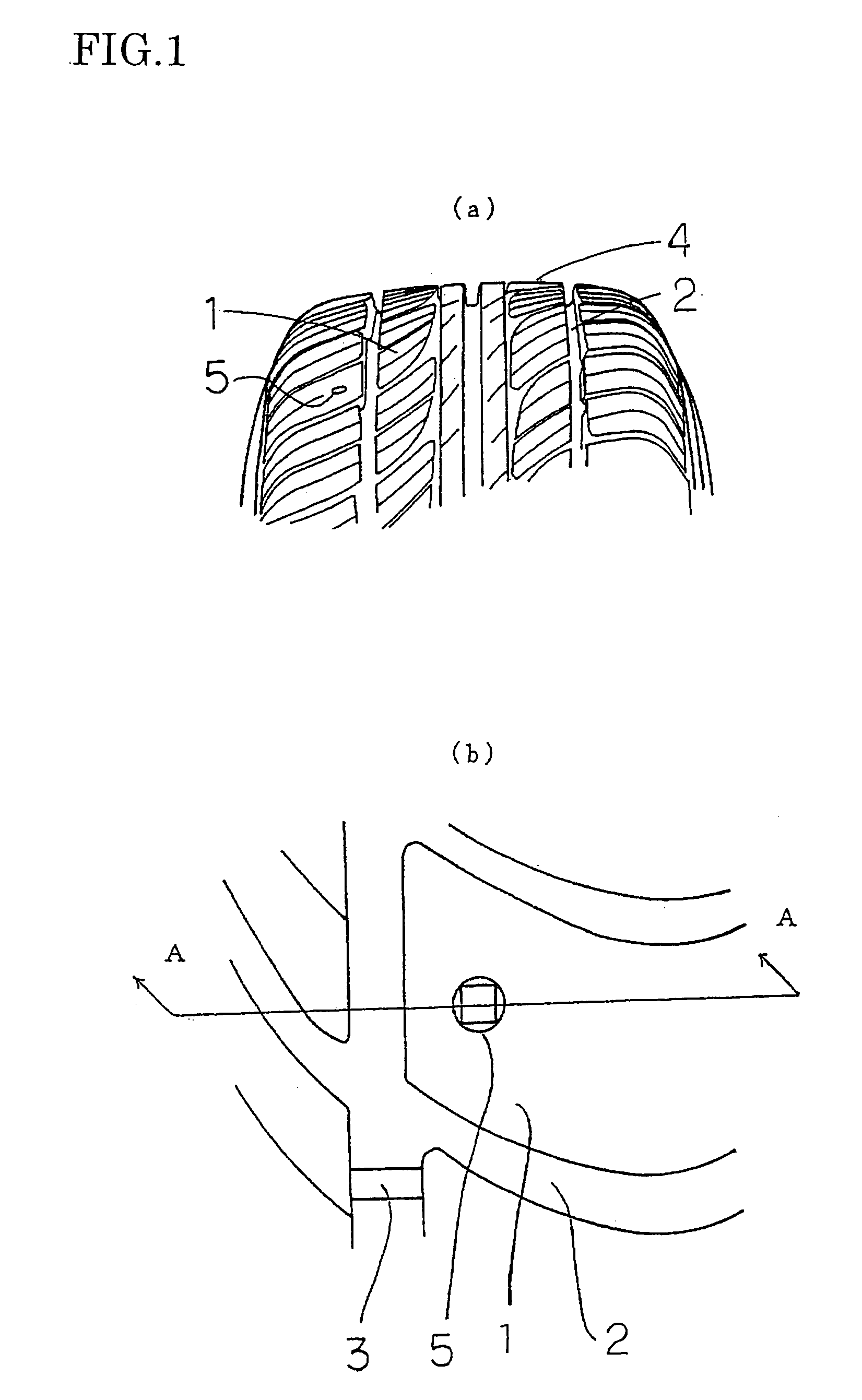
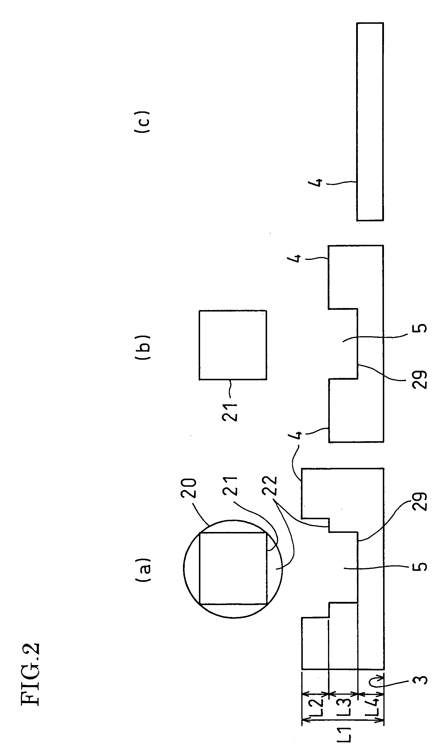
[0028]FIG. 1 and FIG. 2 show an embodiment of a tire having a rotation timing indication hole in accordance with the invention. FIG. 1(a) is a perspective view of a tire which shows a tire tread portion 1, a tread groove 2, and the like. FIG. 1(b) is a partial enlarged view of FIG. 1(a) and shows a wear indicating portion 3 raised from the bottom of the tread groove 2 and one rotation timing indication hole 5 provided in the vicinity of the wear indicating portion 3. The wear indicating portion 3 indicates timing for changing a tire when the degree of wear of the tire reaches a limit for safety and needs to be replaced with a new one. The rotation timing indication hole 5 indicates rotation timing for changing a position where the tire is mounted according to the degree of wear of the tire. This rotation timing indication hole 5 is formed to radially inwardly extend from a tread surface 4 o...


PUM


Abstract

A tire having a rotation timing indication hole of the invention has a rotation timing indication hole comprising a multi-step hole provided in a tire tread, and respective steps of the hole have different contours from each other. Since the contour of the hole changes when the tire is worn, the rotation timing of the tire can be recognized.

Description

TECHNICAL FIELD [0001] The present invention relates to a vehicle tire having an indicator for indicating the rotation timing of a tire. BACKGROUND ART [0002] In order to elongate life of tires mounted on a vehicle, change of positions of tires mounted on the vehicle, so-called rotation (position change) of tires, is performed according to the extent of wear of tire treads (surface of tire). [0003] A tire having a tread wear indicator for indicating timing for the above rotation is known in conventional technologies disclosed in, for example, JP-A-55-110608, JP-UM-B-59-25684, or International Publication No. WO97 / 47483 (JP-T-10-511626). [0004] In these conventional technologies, multi-step holes are formed as rotation timing indication holes in a tire tread, and when a first step of the hole disappears due to wear of the tire, it is determined as a time for rotation of the tire mounting position. [0005] However, in these conventional technologies, since the contour of the rotation t...

Claims


Application Information

Patent Timeline
IPC IPC(8): B60C11/24
CPCY10T152/10027B60C11/24
Inventor FUJII, KENSAKUMURATA, TAKEHIKO
Owner SUMITOMO RUBBER IND LTD
Why Eureka
Try Eureka