Upper beam of roman drapery

a technology of drapery and beam, applied in the direction of shutters/movable grilles, door/window protective devices, wing arrangements, etc., can solve the problems of increased purchase cost, waste of time, and large effort required to activate pull cords, and achieves easy and fast assembly, boosting the competitive power of the drapery, and easy and fast

Inactive Publication Date: 2005-12-08
NIEN LESLIE
View PDF10 Cites 0 Cited by
  • Summary
  • Abstract
  • Description
  • Claims
  • Application Information

AI Technical Summary

Benefits of technology

[0004] It is, therefore, the primary purpose of the present invention to provide an upper beam of Roman drapery, including a Roman-type drapery made up of a drapery body with a coupling section of a proper length disposed at the top edge thereon for a telescopic upper beam to be mounted therein wherein, via the design of movable pieces detachably mounted to folded sections of the drapery body thereof as well as guide sliders and a pulley set disposed at both sides of the telescopic upper beam thereof, the telescopic upper beam is properly adjusted in length, synchronically moving inwards the guide sliders and the pulley set and gathering up in natural wrinkles the drapery body between the guide sliders therewith so as to fit the Roman drapery thereof to any window frames and achieve the widespread use of the present invention thereof.
[0005] It is, therefore, the second purpose of the present invention to provide an upper beam of Roman drapery wherein the telescopic upper beam is detachably engaged with the coupling section of the drapery body thereof, permitting the drapery body to be easily replaced by a new one of various design without the upper beam being changed therewith, facilitating an easier and speedy assembly and achieving various decoration effect of the present invention to boost the competitive power thereof.
[0006] It is, therefore, the third purpose of the present invention to provide an upper beam of Roman drapery wherein a plurality of pull cords are collectively led through the pulley set of the upper beam before individually wound through the guide sliders thereof respectively to avoid the friction problem of the above conventional Roman drapery, facilitating a smoother and effort-saving operation thereof.

Problems solved by technology

There are some drawbacks to such conventional Roman-type drapery 10.
In case the Roman-type drapery 10 purchased is unfit to the size of a window frame, the drapery 10 must be either replaced with a new one or made do for an improper window frame, which is inconveniently limited in decoration as well as assembly thereof Second, the drapery body 12, fixedly attached to the underside of the upper beam 11, must be dismantled along with the upper beam 11 in one set for the replacement of another drapery body 12 of different design, which is quite limited in the replacement thereof and may increase the cost in purchase.
Third, the pull cord 15 is directly wound through the top surface of the upper beam 11 which tends to generate friction at the contact area between the pull cord 15 and the upper beam 11 and result in an awkward operation of the pull cord 15 easily got stuck in the process thereof Thus, great effort is required and wasted to activate the pull cord 15 in operation thereof

Method used


Image

  • Upper beam of roman drapery
  • Upper beam of roman drapery
  • Upper beam of roman drapery

Examples


Embodiment Construction

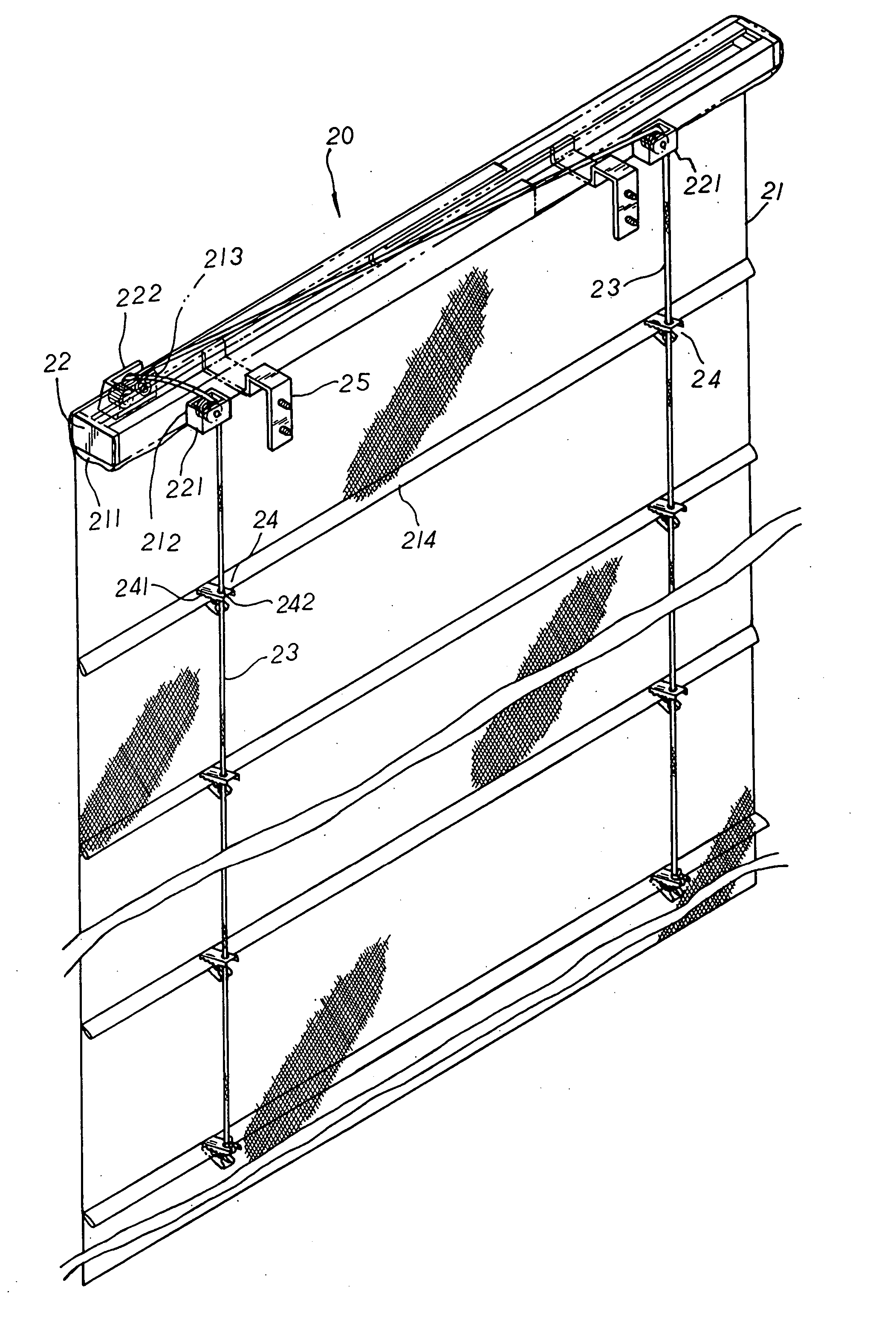
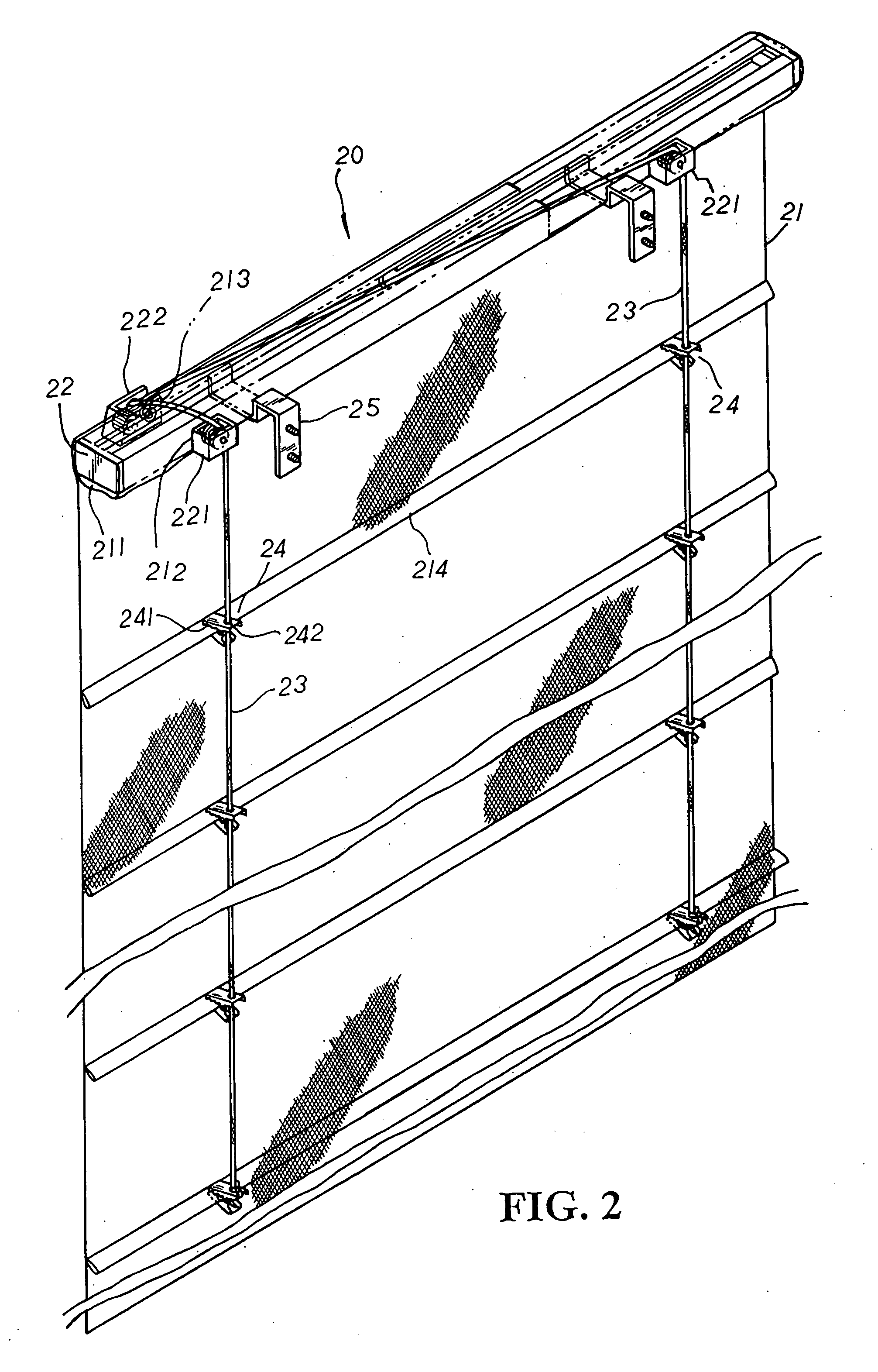
[0012] Please refer to FIG. 2. The present invention is related to an upper beam of Roman drapery, including a Roman-type drapery 20 made up of a drapery body 21 having a coupling section 211 of a proper length disposed at the top edge thereon for a telescopic upper beam 22 to be mounted therein wherein the coupling section 211 thereof is better made into a hollow tubular passage. At the back side of the hollow coupling section 211 thereof is properly disposed a plurality of through holes 212 corresponding to a plurality of guide sliders 221 mounted at the rear side of the telescopic upper beam 22 with each guide slider 221 thereof exposed precisely outside the through hole 212 thereof, and at one front lateral side of the coupling section 211 is provided with a passage hole 213 for a pulley set 222 of the telescopic upper beam 22 to be led there-through and exposed at the outer side thereof. A plurality of pull cords 23 with pulling sections preset for a certain length to suspend d...


PUM


Abstract

An upper beam of Roman drapery includes a Roman-type drapery made up of a drapery body with a coupling section of a proper length disposed at the top edge thereon for a telescopic upper beam to be mounted therein wherein at the rear side of the telescopic upper beam is equipped with a plurality of guide sliders exposed outside through holes of the coupling section, and at the front side of the telescopic upper beam is properly disposed a pulley set exposed outside a passage hole of the coupling section thereof for a plurality of pull cords to be collectively led there-through before individually wound through the guide sliders respectively for smooth operation thereof. The drapery body also has a plurality of folded sections equidistantly arranged at the rear side thereon for movable pieces having clamping parts disposed at one side to be properly attached thereto in alignment with the guide sliders thereof, and the movable pieces also have cord-passage holes disposed at the other side thereof for the pull cords to be sequentially led there-through till fixedly tied up to the bottommost ones thereof. Thus, the telescopic upper beam detachably engaged with the drapery body can be easily adjusted to any window frames, and the drapery body can be speedily replaced by a new one of different design without the upper beam being changed therewith, facilitating an easier and speedy assembly and achieving various decoration effect of the present invention to boost the competitive power thereof.

Description

BACKGROUND OF THE INVENTION [0001] An upper beam of Roman drapery includes a Roman-type drapery made up of a drapery body with a coupling section of a proper length disposed at the top edge thereon for a telescopic upper beam to be mounted therein wherein the telescopic upper beam is equipped with a plurality of guide sliders exposed outside through holes of the coupling section at one side thereof, and a pulley set exposed outside a passage hole of the coupling section at the other side thereof for a plurality of pull cords to be collectively led there-through before individually wound through the guide sliders respectively for smooth operation thereof, and the drapery body is provided with a plurality of folded sections equidistantly arranged at the rear side thereon for movable pieces having clamping parts disposed at one side to be properly attached thereto in alignment with the guide sliders thereof; whereby, the movable pieces as well as the guide sliders and the pulley set th...

Claims


Application Information

Patent Timeline
Patent Type & Authority Applications(United States)
IPC IPC(8): A47H5/14E06B9/262
CPCE06B2009/2622E06B9/262
Inventor NIEN, LESLIE
Owner NIEN LESLIE
Why Eureka
Try Eureka