Center tab bags and dispensers for same providing easy load features

Inactive Publication Date: 2005-12-08
DANIELS MARK E
40 Cites 5 Cited by

AI-Extracted Technical Summary

Problems solved by technology

In contrast, dispensers using bag rolls must await exhaustion of the bag roll or cause a portion of the roll to be wasted in order to have the dispenser refilled.
On the down side, pack type bag dispensers that...

Method used

[0070] (8) In yet another variant, the downward facing hook 285 includes a rounded feature 290 at a lower end 295 o...

Benefits of technology

[0026] (13) In another variant of the invention, a tab stop is provided. The tab stop is mounted to the downward po...

Abstract

A plastic bag and dispenser combination providing easy loading features includes a plurality of bags, each having at least one center tab with a central opening. The tabs are either designed to tear from the bags upon dispensing or to rupture, remaining with the dispensed bag. The dispenser has a downward pointing projection that fits through the opening in the tabs, and a support bar fixed horizontally above the projection. When bags are suspended from the projection at the tabs and located over the support bar, they are ready for individual dispensing. The combination is also applied to T-shirt style bags. The dispenser may be easily loaded as at least one end of the support bar is unattached and the bags may be slipped behind it. Variants of the invention include different configurations of the dispenser for attachment to vertical and horizontal surfaces, under shelves and to other bag dispensers.

Application Domain

BagsSacks +2

Technology Topic

Plastic bagEngineering

Image

  • Center tab bags and dispensers for same providing easy load features
  • Center tab bags and dispensers for same providing easy load features
  • Center tab bags and dispensers for same providing easy load features

Examples

  • Experimental program(1)

Example

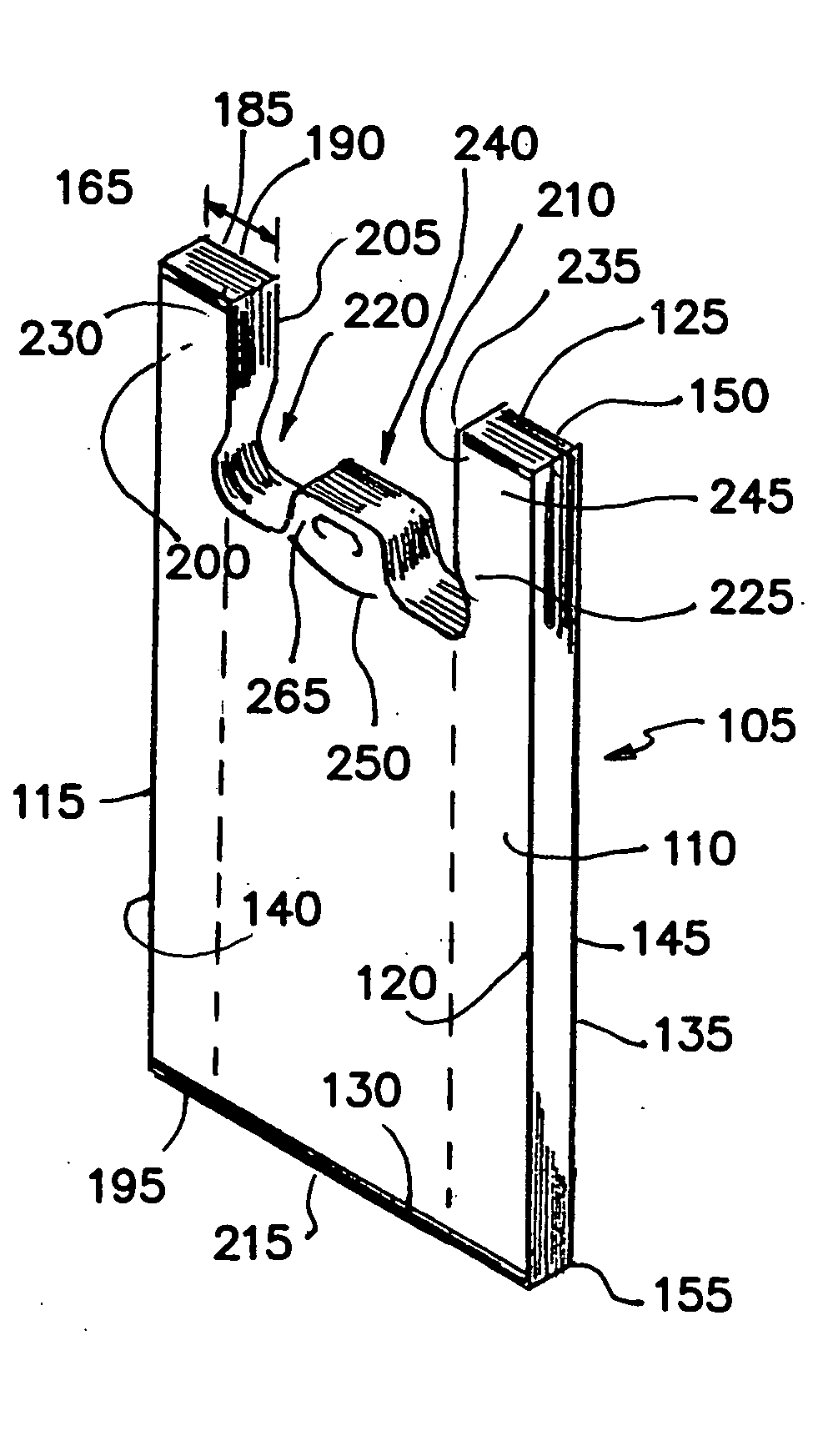
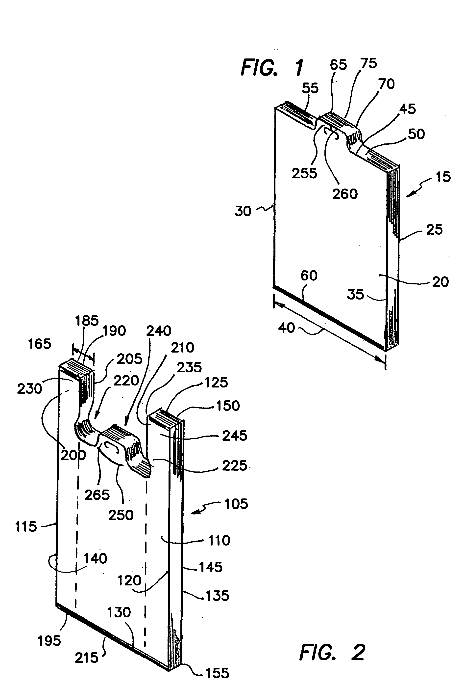
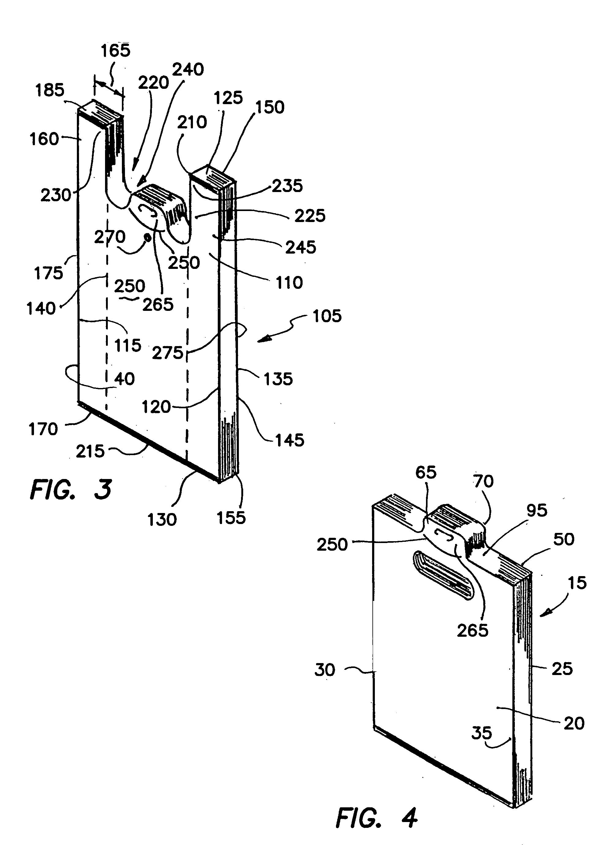
[0060] (1) FIGS. 1, 4 and 6 illustrate a bag and dispenser combination 10 providing the desired features that may be constructed from the following components. As illustrated in FIGS. 1 and 4, a plurality of plastic bags 15 is provided. Each of the bags 15 has a front wall 20, a rear wall 25, first 30 and second 35 parallel linear side edges, a first predetermined width 40, front 45 and rear 50 top edges, an openable mouth 55 and a bottom edge 60. The front 20 and rear 25 walls have at least one front tab 65 or rear tab 70. The tab 65, 70 is located at at least one of the top edges 45, 50 and has an opening 75 therethrough. The opening 75 is sized, shaped and located for suspending the bag 15 from a dispenser 80.
[0061] As illustrated in FIG. 6, a dispenser 80 is provided. The dispenser 80 includes a downward pointing projection 85. The projection 85 is sized and shaped to fit slidably through the opening 75 in the tab 65, 70. A support bar 90 is provided. The support bar 90 has first 95 and second 100 ends and is located horizontally above the projection 85. When the plurality of bags 15 are suspended from the projection 85 at the tab 65, 70 and located over the support bar 90, the bags 15 will be positioned for individual dispensing.
[0062] (2) In a variant of the invention, as illustrated in FIGS. 2 and 3, the bag 15 is a T-shirt style bag 105 that includes a front panel 110. The front panel 110 has first 115 and second 120 parallel linear side edges, a top edge 125 and a bottom edge 130. A rear panel 135 is provided. The rear panel 135 has first 140 and second 145 parallel linear side edges, a top edge 150 and a bottom edge 155. Two front gusset panels 160 of a first predetermined dimension 165 are provided. Each front gusset panel 160 has a top edge 165, a bottom edge 170, first 175 and second 180 parallel side edges. Each front gusset panel 160 is joined at the first side edge 175 to one of the linear side edges 115, 120 of the front panel 110 and extends from the top edge 125 of the front panel 110 to the bottom edge 130 of the front panel 110.
[0063] Two rear gusset panels 185 of the first predetermined dimension 165 are provided. Each rear gusset panel 185 has a top edge 190, a bottom edge 195, first 200 and second 205 parallel side edges and is joined at the first side edge 200 to one of the linear side edges 140, 145 of the rear panel 135 and extends from the top edge 150 of the rear panel 135 to the bottom edge 155 of the rear panel 135. Each front gusset panel 160 also is joined to a respective one of the rear gusset panels 185 at the second side edge 180, 205.
[0064] Each of the front 160 and rear 185 gusset panels is folded inwardly relative to the front 110 and the rear 135 panels. The top edges 125, 150, 165, 190 of the front panel 110, the rear panel 135, the front gusset panels 160 and the rear gusset panels 185 terminate in an upper seam 210. The bottom edges 130, 155, 170, 195 of the front panel 110, the rear panel 135, the front gusset panels 160 and the rear gusset panels 185 terminate in a lower seam 215. The lower seam 215 is perpendicular to the linear side edges 115, 120, 140, 145 of the front 110 and rear 135 panels. A U-shaped cut-out 220 is provided. The U-shaped cut-out 220 is located in an upper portion 225 of the bag 105 and begins at a first point 230 along the upper seam 210 spaced inwardly from the first linear side edge 115, 140 and extends to a second point 235 along the upper seam 210 spaced inwardly from the second linear side edge 120, 145. The cut-out 220 extends downwardly toward the lower seam 215, thereby forming an openable mouth 240 and a pair of bag handles 245, the tab 65, 70 is centrally located on an edge of the openable mouth 240.
[0065] (3) In another variant, as illustrated in FIGS. 2-4, the tab 65, 70 is attached to the openable mouth 55, 240 using a cut line 250 such that as the bag 15, 105 is pulled from the dispenser 80, the tabs 65, 70 will be torn from the bag mouth 240 and remain on the projection 85.
[0066] (4) In still another variant, as illustrated in FIGS. 1 and 6, the tab 65, 70 includes a rupturable feature 255. The rupturable feature 255 connects to the opening 75 and extends toward a perimeter 260 of the tab 65, 79. When the bag 15, 105 is pulled from the dispenser 80, the rupturable feature 255 provides a connection between the opening 75 and the perimeter 260, permitting the bag 15, 105 to be removed from the projection 85 without leaving a portion 265 of the tabs 65, 70 on the projection 85, as illustrated in FIGS. 2-4.
[0067] (5) In a further variant, as illustrated in FIG. 3, the bags 105 include means 270 for removably attaching an upper portion 275 of the rear panel 135 of a first bag 105 to an upper portion 280 of the front panel 110 of a second, adjacent registered bag 105. When the first bag 105 is pulled from the dispenser 80, the rear panel 135 will pull the front panel 110 of the second bag 105 forward, causing the second bag 105 to open.
[0068] (6) In still a further variant, the means 270 for removably attaching the upper portion 275 of the rear panel 135 of the first bag 105 to the upper portion 280 of the front panel 110 of the second, adjacent registered bag 105 is selected from the group that includes glue spotting, corona treatment, hot pinning, cold staking and compression.
[0069] (7) In another variant of the invention, as illustrated in FIGS. 5-12, the projection 85 includes a downward facing hook 285.
[0070] (8) In yet another variant, the downward facing hook 285 includes a rounded feature 290 at a lower end 295 of the hook 285, the rounded feature 290 is designed to prevent injury and unwanted tearing of the bag tabs 65, 70.
[0071] (9) In still another variant, as illustrated in FIG. 6, the support bar 90 has a length 300 greater than the first predetermined width 40.
[0072] (10) In a further variant, as illustrated in FIG. 6, the support bar 90 has bag control features 305 located at the first 95 and second 100 ends.
[0073] (11) In still a further variant, as illustrated in FIG. 6, the bag control features 305 include upwardly angled projections 310. The projections 310 are sized, shaped and located to prevent lateral movement of the bags 15, 105.
[0074] (12) In yet a further variant, as illustrated in FIG. 8, the bag control features 305 include rounded ends 315. The rounded ends 315 are sized, shaped and located to prevent lateral movement of the bags 15, 105.
[0075] (13) In another variant of the invention, as illustrated in FIGS. 9-11, a tab stop 320 is provided. The tab stop 320 is mounted to the downward pointing projection 85 above a lower end 325 of the projection 85 and prevents upward movement of bag tabs 65, 70 beyond the tab stop 320.
[0076] (14) In still another variant, as illustrated in FIGS. 5, 6, 9, 10 and 11, the support bar 90 is attached at the second end 100 to a spacing bracket 330. The spacing bracket 330 locates the support bar 90 at a first predetermined distance 335 outward from the bracket 330 such that a bag pack 340 will fit slidably between the bracket 330 and the support bar 90.
[0077] (15) In a further variant, as illustrated in FIGS. 5, 6, 9 and 10, the downward pointing projection 85 is attached to the spacing bracket 330.
[0078] (16) In still a further variant, as illustrated in FIGS. 7 and 8, the downward pointing projection 85 is attached to the support bar 90.
[0079] (17) In yet a further variant, as illustrated in FIGS. 5, 9 and 11, the dispenser 80 includes a mounting fixture 345. The mounting fixture 345 is attached to the spacing bracket 330.
[0080] (18) In another variant of the invention, as illustrated in FIGS. 5, 7, 8 and 12, the bag and dispenser combination 10 includes at least one additional downward pointing projection 350. The additional projection 350 is located below the projection 85.
[0081] (19) In still another variant, as illustrated in FIG. 5, the additional projection 350 extends outwardly toward the support bar 90 further than the projection 85.
[0082] (20) In yet another variant, as illustrated in FIG. 7, the support bar 90 is attached at the second end 100 to a horizontal surface mount 355 and the downward pointing projection 85 is attached to the support bar 90.
[0083] (21) In a further variant, as illustrated in FIG. 8, the support bar 90 is attached at the second end 100 to a vertical surface mount 360 and the downward pointing projection 85 is attached to the support bar 90.
[0084] (22) In still a further variant, as illustrated in FIG. 13, the support bar 90 is attached at the second end 100 to another bag dispenser 365.
[0085] (23) In yet an further variant, as illustrated in FIG. 10, the spacing bracket 330 is attached to another bag dispenser 365.
[0086] (24) In another variant, as illustrated in FIG. 14, a U-shaped bracket 370 is provided. The bracket 370 has a first vertical side 375, a second vertical side 380 spaced from the first side 375 and a connecting lower portion 385. The first vertical side 375 has features for attaching the vertical side 375 to a vertical surface 390. The support bar 90 is attached orthogonally to an upper end 395 of the second vertical side 380. The downward pointing projection 85 is attached to the second vertical side 380 at a point 400 spaced downwardly from the support bar 90.
[0087] (25) In yet another variant, as illustrated in FIG. 11, the spacing bracket 330 is attached to an L-shaped bracket 405. The L-shaped bracket 405 extends above or below the support bar 90 and has at least one hole 410 through it for attachment to a horizontal surface 415.
[0088] (26) In still another variant of the invention, as illustrated in FIG. 12, the support bar 90 is centrally attached to a vertical member 420. The vertical member 420 is attached at a lower end 425 to a base 430 for securing the dispenser 80 to a horizontal surface 415. The vertical member 420 has at least one of the downward pointing projections 85, 350 attached to its front surface 435.
[0089] (27) In yet a further variant, as illustrated in FIG. 15, the spacing bracket 330 is attached to a vertical support 440. The vertical support 440 is attached at a lower 445 end to a base 450.
[0090] (28) In still a further variant, a reinforcing section 455 is provided. The reinforcing section 455 is attached to the support bar 90 at a first end 460 and attached to the vertical support 440 at a second end 465.
[0091] (29) In another variant of the invention, the base 450 is sized and shaped to secure the dispenser 80 to either a horizontal surface 415 or a vertical surface 390.
[0092] (30) In a final variant, the base 450 is sized and shaped to secure the dispenser to a railing 470.
[0093] The Center Tab Bags and Dispensers for Same Providing Easy Load Features 10 have been described with reference to particular embodiments. Other modifications and enhancements can be made without departing from the spirit and scope of the claims that follow.

PUM

no PUM

Description & Claims & Application Information

We can also present the details of the Description, Claims and Application information to help users get a comprehensive understanding of the technical details of the patent, such as background art, summary of invention, brief description of drawings, description of embodiments, and other original content. On the other hand, users can also determine the specific scope of protection of the technology through the list of claims; as well as understand the changes in the life cycle of the technology with the presentation of the patent timeline. Login to view more.

Similar technology patents

Granule drier

InactiveCN108507280AReduce energy consumptionprevent upward movement
Owner:JIANGSU SHENYUAN MATERIAL SCI CO LTD

Classification and recommendation of technical efficacy words

  • prevent upward movement

Granule drier

InactiveCN108507280AReduce energy consumptionprevent upward movement
Owner:JIANGSU SHENYUAN MATERIAL SCI CO LTD
Why Eureka
Try Eureka