
Method and apparatus for monitoring integrity of wires or electrical cables

a technology of integrity monitoring and wires, applied in the direction of pulse reflection methods, line-transmission details, instruments, etc., can solve the problems of greater ac resistance, mismatch between the impedance at the fault location and the impedance at the non-fault location, and dissipation of the energy of the applied field

Inactive Publication Date: 2005-12-08
CM TECH CORP
View PDF17 Cites 18 Cited by
  • Summary
  • Abstract
  • Description
  • Claims
  • Application Information

AI Technical Summary

Benefits of technology

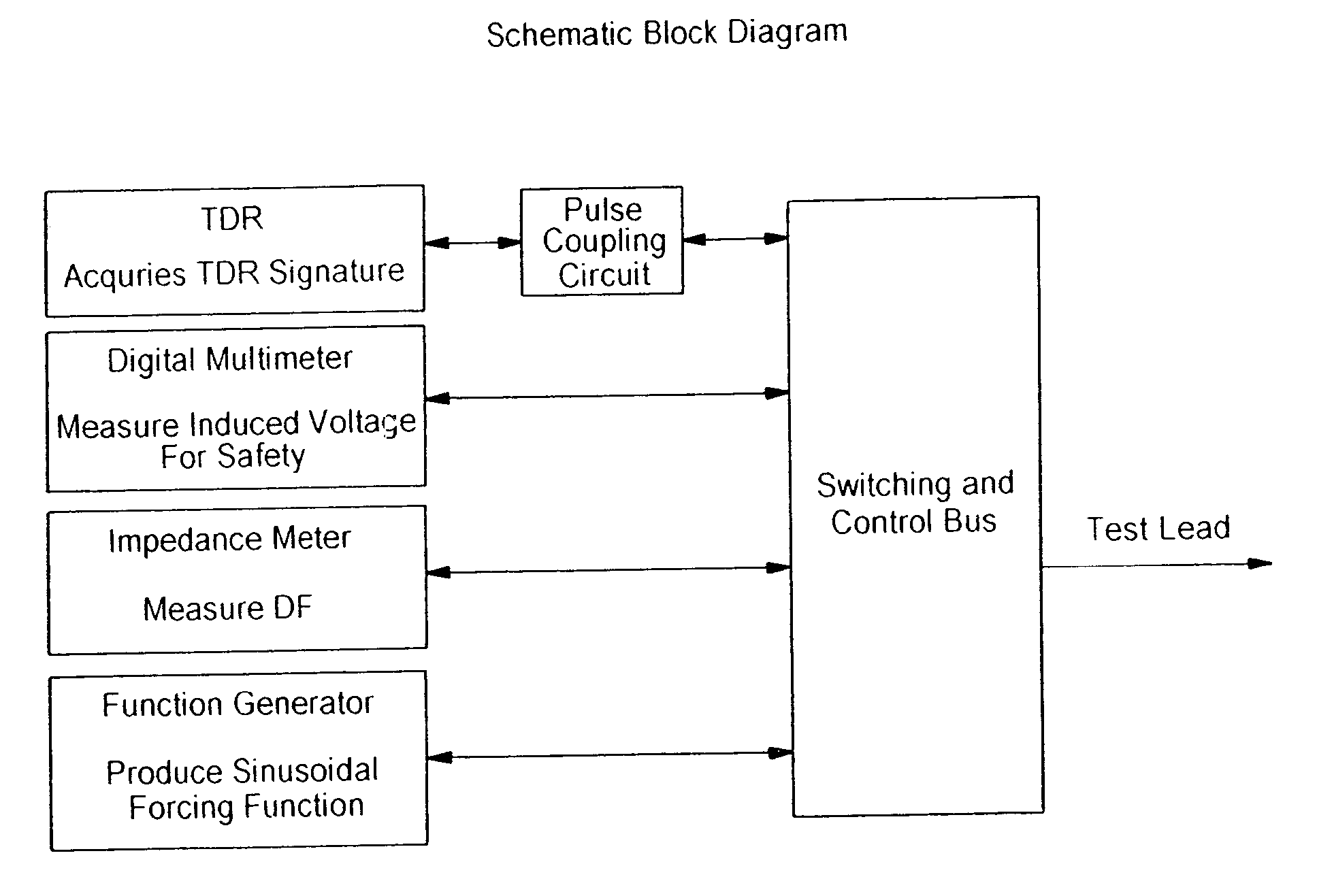
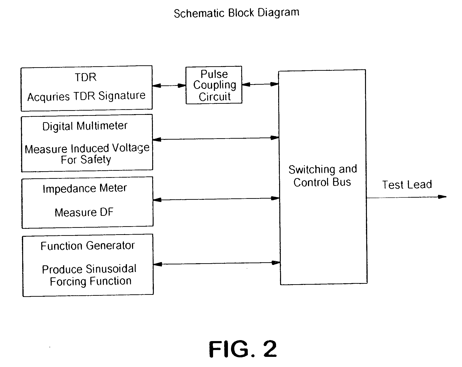
The present invention is a method and apparatus that combines traditional TDR and DF measurement techniques to monitor the integrity of wires and devices connected to wires. The apparatus includes a pulse generator, function generator, and detector to measure changes in dissipation factor values along the wire caused by defects or faults. The technical effect of this invention is to provide a more accurate and reliable method for monitoring the integrity of wires and devices connected to wires.

Problems solved by technology

Where there is a fault in the wire under test, the normal impedance of the wire is changed, resulting in a mismatch between the impedance at the fault location and the impedance at a non-fault location.
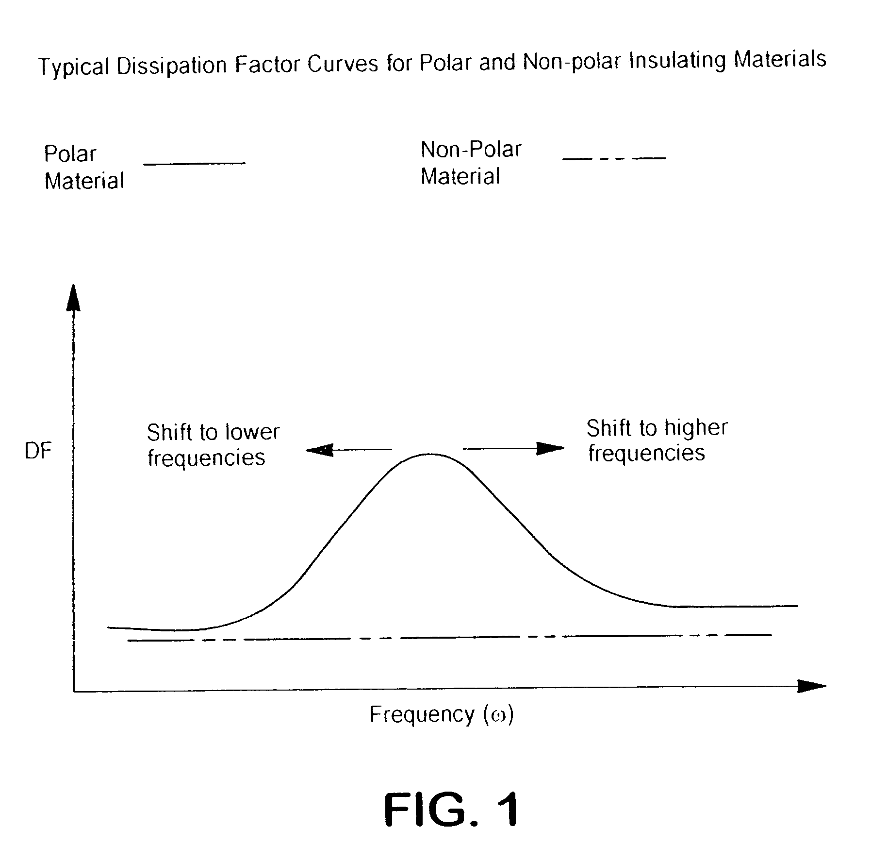
This alternating electric field causes any polar dielectric molecules in the dielectric insulation material, such as undesirable water molecules, to also alternate (to align with the field), resulting in the dissipation of energy of the applied field.
Increased brittleness, in turn, results in greater AC resistance of the molecular motion described above, and hence greater dissipation and higher DF measurements.
Existing fault-detection technology suffers from a number of problems.
For example, currently known methods are often inadequate to detect small defects in a wire, such as nicks, chafing, and poor connector contacts, because existing technology is not sensitive enough and yields results (e.g. TDR signatures) that are insufficiently precise.
But these types of small defects are of particular importance because, while they do not impair operation of the wiring, they have the potential to become full-fledged faults in the wiring that could cause a severe malfunction while the device connected to the wiring is in operation.
Indeed, the very fact that these small defects do not yet impair operation may hinder their detection and thereby exacerbate the problem.
Defects such as nicks, chafing, and poor connector contacts are common in aircraft wiring, due, for example, to mechanical abrasion, fluid contamination (by water, hydraulic fluid or other fluids used in aircraft), or heat stress.
Also, the particular types of wire insulation commonly used on aircraft are known to acquire similar kinds of small defects as they age.
For example, polyimide (Kapton®) insulated wire is known to develop radial cracks over time.
Initially, the crack may have no effect on the wire's operation, but it could gradually grow to encircle the entire wire, resulting eventually in a bare, uninsulated wire.
In addition, aircraft generally employ wires which are short and unshielded.
Both of these characteristics of aircraft wiring pose difficulties for TDR.
TDR is known to have problems in accurately locating a fault a short distance from the injection point, because errors in measurement of the travel time of the TDR pulse have a more significant effect.
Again, the non-uniform geometry of unshielded wires yields a less smooth waveform (TDR signature), which is more difficult to interpret.
Another limitation of conventional fault-detection technology is that it requires the use of a baseline or reference value obtained from a faultless wire.
However, the acquisition of this data is not always possible.
Even if baseline data is subsequently obtainable, it may be time-consuming to obtain it.

Method used


Image

  • Method and apparatus for monitoring integrity of wires or electrical cables
  • Method and apparatus for monitoring integrity of wires or electrical cables
  • Method and apparatus for monitoring integrity of wires or electrical cables

Examples


Embodiment Construction

[0035] The method and apparatus of the present invention may be used to test wiring, for example, for periodic routine maintenance, post-installation verification, or troubleshooting, in order to prevent or resolve performance problems caused by defects, damage or deterioration due to aging or environmental factors. The present invention may also be used to determine the location, type and magnitude of a defect or fault in an installed wire or in a device connected to a wire.

[0036] The terms “fault” and “defect” are both used to refer to that which is a deviation from a virgin wire. But a “defect” is distinguished from a “fault” in that the presence of a defect does not affect the operation of the wire or the circuit containing the wire, whereas the presence of a “fault” adversely affects the operation of the wire or circuit containing the wire. An example of a fault would be an open or short circuit, and an example of a defect could be a wire having nicked or chafed insulation.

[0...


PUM


Abstract

An apparatus for monitoring the integrity of a wire is provided, which includes a TDR instrument for generating a pulse waveform for transmission through the wire. The apparatus also includes a function generator for generating an electrical or non-electrical forcing waveform for transmission through the wire. The pulse waveform is transmitted through the wire in combination with the forcing waveform and a detector measures a change in dissipation factor values along the wire.

Description

CROSS REFERENCE TO RELATED APPLICATION [0001] This application is a continuation-in-part of U.S. patent application Ser. No. 10 / 066,197, filed on Jan. 31, 2002, now U.S. Pat. No. ______, which claims, the benefit of, and incorporates by reference, U.S. Provisional Patent Application No. 60 / 265,117, filed Jan. 31, 2001. The entire disclosure of each prior patent application is incorporated herein by reference.BACKGROUND OF THE INVENTION [0002] 1. Field of the Invention [0003] The present invention pertains to a method and apparatus for monitoring the integrity of wires or electrical cables, or the like, including but not limited to detecting faults or defects in the same. [0004] 2. Related Background Art [0005] Various methods for monitoring the integrity of wires, such as detecting faults in a wire, are known. One such method is time domain reflectometry (TDR). TDR operates as follows. First, a fast rise time pulse is injected into a wire. Then, if the pulse encounters an impedance ...

Claims


Application Information

Patent Timeline
Patent Type & Authority Applications(United States)
IPC IPC(8): G01R31/02G01R31/11
CPCG01R31/008G01R31/11G01R31/021G01R31/58
Inventor ALLAN, GREGORYALSTINE, ROLLIN VAN
Owner CM TECH CORP
Learn More