Ink container

a technology of ink containers and ink bottles, applied in printing and other directions, to achieve the effect of preventing air bubbles from lowering, stabilizing the supply of ink, and reducing the detection delay of remaining ink amoun

Inactive Publication Date: 2005-12-08
CANON KK
View PDF9 Cites 69 Cited by
  • Summary
  • Abstract
  • Description
  • Claims
  • Application Information

AI Technical Summary

Benefits of technology

[0039] According to an aspect of the present invention, there is provided an ink container comprising an ink accommodation chamber for directly accommodating ink; a sensor portion for detecting a remaining amount of the ink in said ink accommodation chamber, wherein ambient air is introduced from an outside of said ink accommodation chamber into the ink in accordance with supplying the ink into an ink jet recording head; a division wall extended from an inner bottom portion of said ink accommodation chamber substantially upwardly, said division wall divides a space between an ambient air introducing portion which introduces the air into the ink in said ink accommodation chamber and said sensor portion to permit passage of the ink therethrough and to prevent passage, therethrough, of bubbles which are produced with introduction of the air. With such a structure, the bubbles produced by the gas-liquid exchange are substantially prevented from entering the section in which the sensor portion is provided in the ink accommodation chamber by the division wall. Therefore, the ink supply can be stabilized even when the printing speed is increased or the ink supply amount is increased in ink jet recording, and the delay in the remaining ink amount detection in the case of using the sensor portion can be avoided.
[0040] According to an aspect of the embodiment of the present invention, the provision of the division wall substrate between the sensor portion and the ambient air introducing portion in the ink accommodation chamber, is effective to substantially prevent the air bubbles from approaching to the sensor portion for detecting the remaining ink amount, thus quickly directing the bubbles upward from the bottom surface of the ink accommodation chamber, and / or substantially prevent the air bubbles from lowering with the lowering of the ink liquid surface. Thus, even if the continuous print with high printing duty is carried out, the erroneous detection of the remaining ink amount can be effectively prevented, thus accomplishing a highly reliable ink container.

Problems solved by technology

The problem arising from a droplet of ink remaining on the reflecting surface with the result of malfunction is known, but the problem arising from the relationship between the bubbles and the optical reflection member in an ink container wherein gas-liquid exchanging operation occurs is not known.

Method used


Image

  • Ink container
  • Ink container
  • Ink container

Examples


embodiment 1

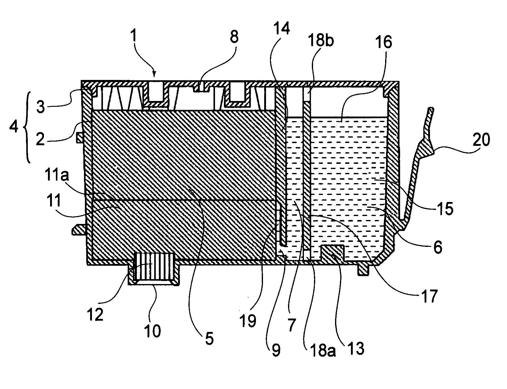
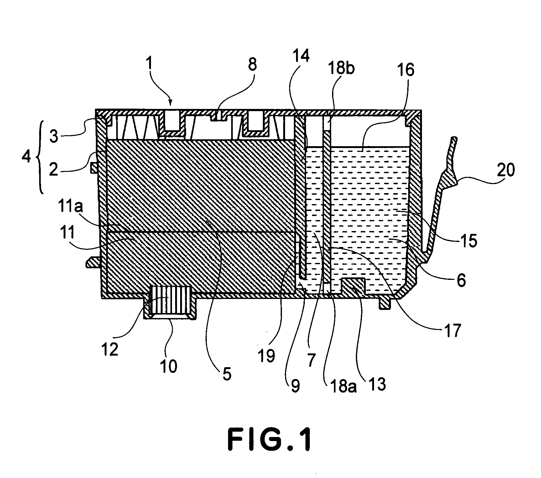
[0068]FIG. 1 is a schematic sectional view of the ink container 1 according to Embodiment 1 of the present invention. In FIG. 1, the ink container 1 comprises a case 2 which opens at the upper portion, and a cap 3 covering the negative pressure generating member accommodating chamber 5 and the ink accommodation chamber 6. The partition wall 14 partitions the ink container into a negative pressure generating member accommodating chamber 5 which accommodates the negative pressure generating member 11, is in fluid communication with the ambient air at the upper portion and is in fluid communication with the ink supply port 10 at the lower portion, and the ink accommodation chamber 6 substantially hermetically sealed and accommodating the ink 15. The lower portion of the partition wall 14 is provided with a communicating portion 9 (opening) for permitting fluid communication between the negative pressure generating member accommodating chamber 5 and the ink accommodation chamber 6.

[006...

embodiment 2

[0079]FIG. 5, (b) is a substantial sectional view of an ink cartridge according to Embodiment 2 of the present invention, which is applied to an ink cartridge comprising integral recording head portion 53 and the ink container 50. FIG. 5, (a) shows a conventional ink cartridge.

[0080] The structure and operation of the right hand side of the ink supply tube 52 for connection between the recording head 53 and the ink container in the Figure, are the same as with Embodiment 1, and therefore, the detailed description thereof is omitted for simplicity, and the same reference numerals as with the foregoing embodiment are assigned to the elements having the corresponding functions.

[0081] In the conventional structure, as shown in FIG. 5, (a), a surface of the partition wall 14 is used as the optical reflection member, and an optical sensor 1071 is provided opposed to the partition wall 14. Infrared light from a light emitting portion 1072 of the optical sensor 1071 is once reflected and ...

embodiment 3

[0083]FIG. 6 shows an ink container according to Embodiment 3 of the present invention, wherein the ink 1112 is directly accommodated in the container, and there is the air in an upper space 1117 of the container. The bottom surface of the container is provided with an ink supply port 1113 closed by a plug urged by an elastic member. The bottom portion of the ink container is provided with an air vent 1114 in the form of a fine opening for introduction of the ambient air. The diameter, the configuration and the ink property are such that meniscus force is provided to generate a negative pressure in the container. With supply of the ink 1112 from the ink supply port 1113 into the ink jet recording head (unshown), the gas-liquid interface 1116 lowers, and the bubble 1118 is introduced into the upper space 1117 through the air vent 1114.

[0084] The bottom portion of the ink container is provided with an optical reflection member 1119 for detecting the remaining ink amount.

[0085] Simil...


PUM


Abstract

An ink container includes an ink accommodation chamber for directly accommodating ink; a sensor portion for detecting a remaining amount of the ink in said ink accommodation chamber, wherein ambient air is introduced from an outside of said ink accommodation chamber into the ink in accordance with supplying the ink into an ink jet recording head; a division wall extended from an inner bottom portion of said ink accommodation chamber substantially upwardly, said division wall divides a space between an ambient air introducing portion which introduces the air into the ink in said ink accommodation chamber and said sensor portion to permit passage of the ink therethrough and to prevent passage, therethrough, of bubbles which are produced with introduction of the air.

Description

FIELD OF THE INVENTION AND RELATED ART [0001] The present invention relates to an ink container for accommodating ink to be supplied to an ink jet recording head, and an ink jet recording apparatus usable with an ink container. [0002] A detection of remaining ink amount will first be described. [0003] An ink container used with a field of an ink jet recording has a limited ink accommodation capacity to continuously supplying the ink to a recording head for ejecting the ink, and is detachably mountable to a recording device. When the ink is used out of the ink container is exchanged with a fresh ink container, and the ink supply is possible until the lifetime of the recording device (recording head) ends. [0004] In order to detect the short of the ink in the ink container, various structures have been proposed and are put into practice. More particularly, there are a method in which an electric conductivity of the ink is used to detect whether or not the ink level (height of the ink ...

Claims


Application Information

Patent Timeline
Patent Type & Authority Applications(United States)
IPC IPC(8): B41J2/175
CPCB41J2/17566B41J2/17513B41J2/17503
Inventor YAMAMOTO, HAJIME
Owner CANON KK
Why Eureka
Try Eureka