Gravity sensor

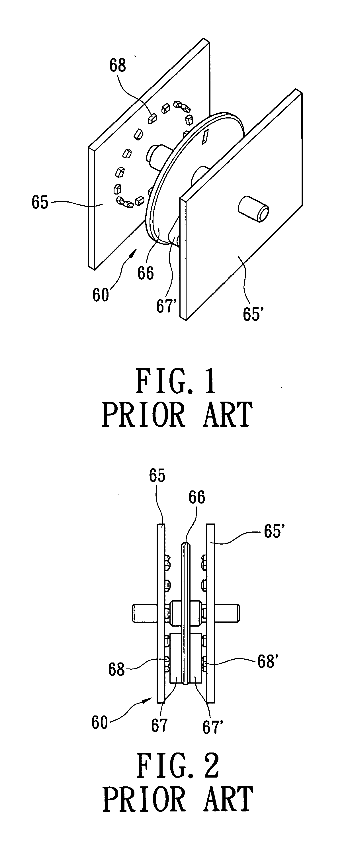
a gravity sensor and sensor technology, applied in the field of gravity sensors, can solve the problems of b>68/b>, b>68/b>′, and b>68/b>′ to suffer from wear after long-term us

Inactive Publication Date: 2005-12-08
MULLER CAPITAL
View PDF2 Cites 0 Cited by
  • Summary
  • Abstract
  • Description
  • Claims
  • Application Information

AI Technical Summary

Benefits of technology

[0004] It is an object of the present invention to provide a gravity sensor to overcome a wear problem by using a photo interrupter instead of a contact-type varistor.

Problems solved by technology

However, the electro brushes 67 and 67′ and varistors 68 and 68′ may suffer from wear after long-term use.

Method used


Image

  • Gravity sensor
  • Gravity sensor
  • Gravity sensor

Examples


Embodiment Construction

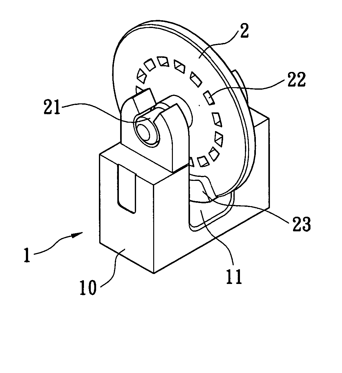
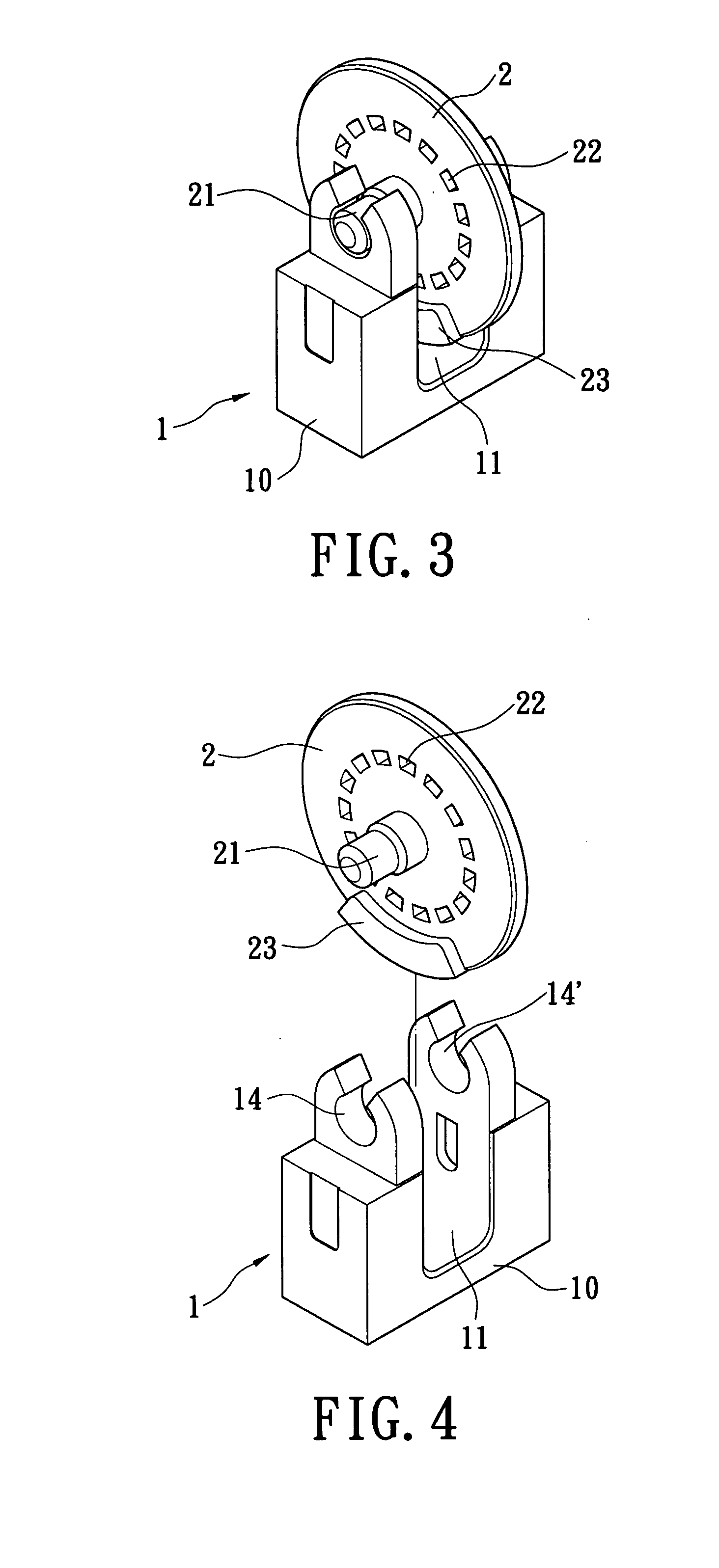
[0020] The gravity sensor has extensive application. For example, the gravity sensor can be used in a joystick to detect an inclined angle of the joystick. With reference to FIGS. 3 to 8, the gravity sensor according to the present invention mainly comprises a photo interrupter 1 and a gravity wheel 2. The photo interrupter 1 comprises a housing 10, a cavity 11 in the housing 10, a light emitter 12 on one side of the housing 10 and a light detector 13 on the other side of the housing 10. The light emitted from the light emitter 12 will be directly detected by the light detector 13 if there is no obstacle which is present in the cavity 11. Alternatively, the output of the light detector 13 will change if there is an obstacle which is present in the cavity 11. In a preferred embodiment of the present invention, the light emitter 12 can be an infrared light emitting diode (LED), and the light detector 13 comprises two photo transistors S1 and S2 on a light receiving plane thereof to ge...


PUM


Abstract

A gravity sensor has a photo interrupter and a gravity wheel. The photo interrupter has a housing, a cavity in the housing, a light emitter on one side of the housing and a light detector on the other side of the housing. The gravity wheel points in a direction of gravity and has a pivot at center thereof and pivotally arranged on the housing, a plumb at one edge of the gravity wheel and a plurality of through holes annularly arranged in the gravity wheel. The gravity wheel has a portion present in the cavity. An inclined angle of a test object is determined by calculating relative movement between the photo interrupter and the gravity wheel.

Description

FIELD OF THE INVENTION [0001] The present invention relates to a gravity sensor, and especially to a contactless gravity sensor to overcome a wear problem. BACKGROUND OF THE INVENTION [0002] The prior art position sensor in a joystick generally comprises a contact-type varistor controller. As shown in FIG. 1, the contact-type varistor controller 60 comprises two shielding plates 65 and 65′, a control wheel 66 pivotally arranged between the two shielding plates 65 and 65′, electro brushes 67 and 67′ arranged on outer facers of the control wheel 66, varistors 68 and 68′ annularly arranged on inner facers of the shielding plates 65 and 65′, respectively. [0003] However, the electro brushes 67 and 67′ and varistors 68 and 68′ may suffer from wear after long-term use. The contact-type varistor controller 60 is degraded and thus has a shorter work life. SUMMARY OF THE INVENTION [0004] It is an object of the present invention to provide a gravity sensor to overcome a wear problem by using ...

Claims


Application Information

Patent Timeline
Patent Type & Authority Applications(United States)
IPC IPC(8): G01C9/06G01C9/12G01D5/34G01J1/42
CPCG01C9/12G01C2009/066
Inventor CHEN, CHENG-FANGSU, CHENG-HONG
Owner MULLER CAPITAL
Why Eureka
Try Eureka