Actuator assembly for locking device

a technology of locking device and actuator assembly, which is applied in the field of locking devices, can solve the problems of large difference in rotation speed, change of battery voltage, and difficulty in controlling the stroke of pin with respect to the coil spring, so as to reduce or prevent the jitter or jump of the spring, reduce the friction between the pin and the actuator assembly, and improve the ability of limiting the radial jittering of the cylindrical spring. , the effect of reducing the jitter or jumping of the spring

Active Publication Date: 2020-06-23
SHANGHAI BUDDY TECHONOLOGICAL
View PDF11 Cites 1 Cited by
  • Summary
  • Abstract
  • Description
  • Claims
  • Application Information

AI Technical Summary

Benefits of technology

[0008]Therefore, it is a primary objective of the present invention to provide an actuator assembly of a lock with simple structure and high safety and reliability.
[0020]1. The structure of two retaining rings and the second sliding groove of casing is adopted, and the retaining ring is contacted with a bevel or arc surface of the second sliding groove, and the force is uniformly received, so as to effectively reduce or prevent the jitter or jumping of the spring during the process of rotating the pin along the cylindrical spring.
[0021]2. The two half casings are combined to form the cavity structure. Compared with the conventional frame, the invention changes the plan that limits the axial jitter of the cylindrical spring into a uniform arc surface disposed along the circumference of the cylindrical spring, so as to improve the ability of limiting the radial jittering of the cylindrical spring and the operating reliability of the actuator assembly. In addition, the buckles installed to the two half casings and the rivets can overcome the problems of fixing the half casings securely and positioning them accurately.
[0022]3. The invention uses the bearing shell made of an oily material and installed on the drive shaft and operated with the pin to change the sliding friction into the rolling friction, so as to significantly reduce the friction between the pin and the cylindrical spring and effectively overcome the wearing problem of the pin and the cylindrical spring.
[0023]4. The present invention uses a smaller amount of components and has the features of simple structure, to facilitate manufacturing and installation.

Problems solved by technology

Due to cost reasons, the combination lock generally uses a micro DC motor.
However, the micro DC motor has the disadvantages of a wide dispersion of parameters in its manufacturing process, a change of battery voltage, and a large difference of its rotation speed, and it is very difficult to control the stroke of the pin with respect to the coil spring even when a reducer gear set is used and the power-on time is controlled.
Most of the time, the pin may slip or jam when it moves to a distal end of the spring (for the last turn of the spring) and if the motor is still not powered off.
As a result, a relatively larger friction may be produced or the spring may be jittered and twisted easily.
These results not just wear out or damage the spring and slider only, but also cause the pin being locked-rotor into the spiral track of the spring.
In addition, the friction produced between the pin and the spring may wear out or damage the pin and the spring.
However, P.R.C. Pat. No. CN201110244325.0 has not disclosed any technical solution to overcome the problem of wearing out the pin and the spring.
In summation, the problem related to the jitter and jumping of the spring may be overcome by the aforementioned or other technical solutions, but the problem of wearing out the pin and the spring still remains unsolved.

Method used


Image

  • Actuator assembly for locking device
  • Actuator assembly for locking device
  • Actuator assembly for locking device

Examples


Embodiment Construction

[0034]The above and other objects, features and advantages of this disclosure will become apparent from the following detailed description taken with the accompanying drawings.

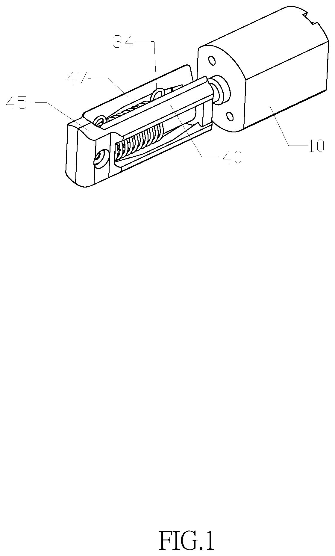
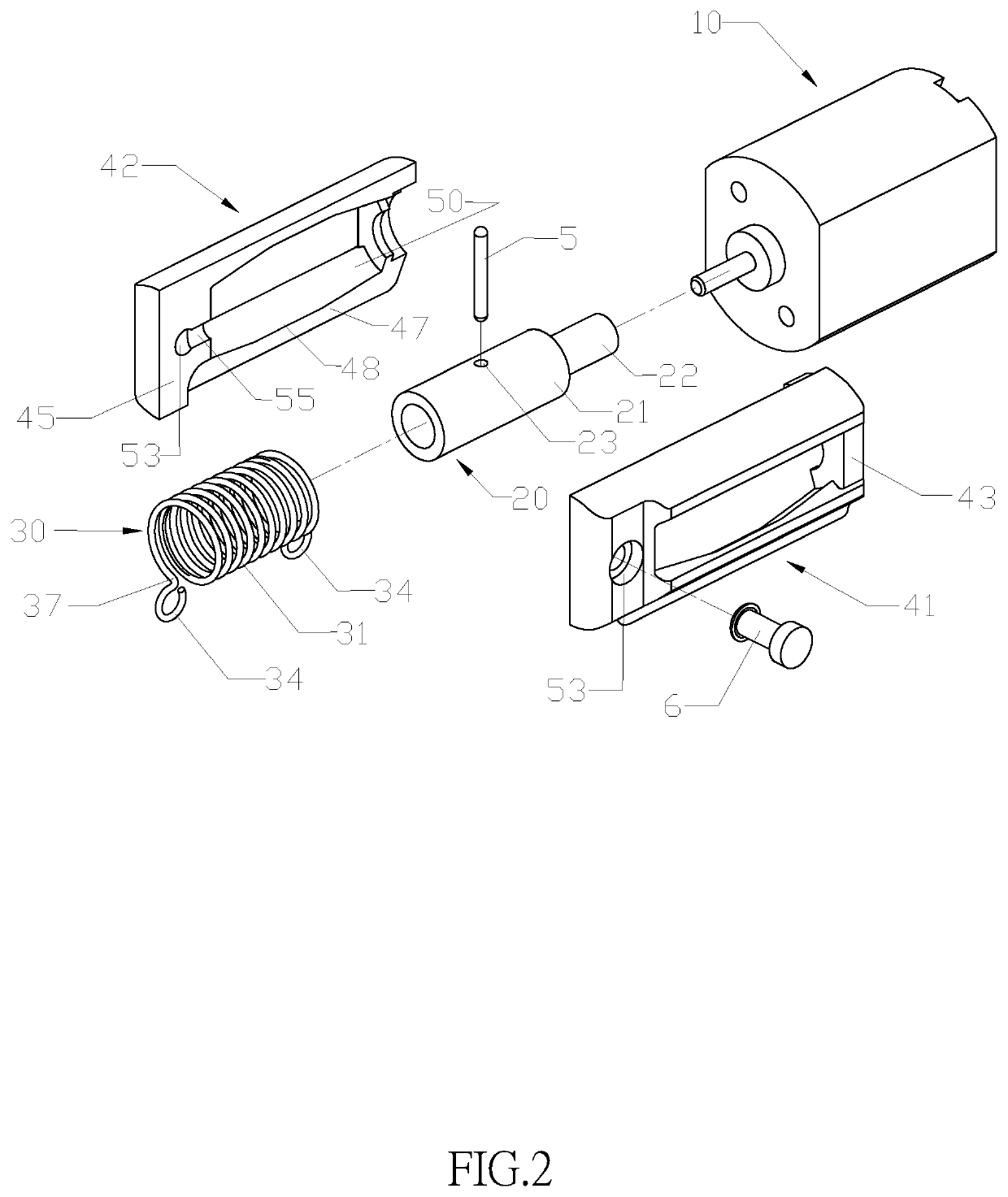
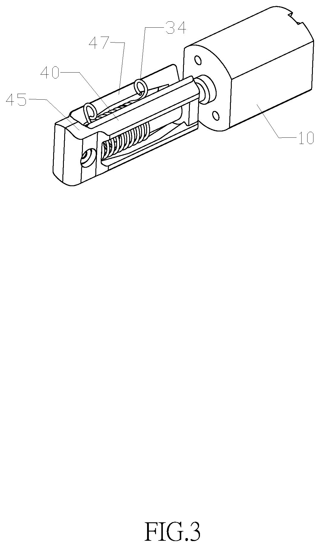
[0035]With reference to FIGS. 1 and 2 for the structure of the first preferred embodiment of the present invention and FIGS. 3 and 4 for the structure of the second preferred embodiment of the present invention, both preferred embodiments comprise a motor 10, a drive shaft 20, and a casing 40 which are the same in both embodiments, and the shape and size of the whole actuator assembly are the same in both embodiments, except that the retaining rings of a coil spring 30 and a coil spring 35 are different and whether or not a bearing shell matched with a pin 5 is adopted. Both of the coil spring 30 and coil spring 35 include a cylindrical spring 31 and two retaining ring 34 symmetrically installed at both ends of the cylindrical spring 31, wherein the cylindrical spring 31 is the same in both embodiments, and th...


PUM


Abstract

The invention relates to the technical field of locks and discloses an actuator assembly of a combination lock. The actuator assembly includes a fixed motor, a drive shaft fixed to the axis of the motor, a cylindrical spring sheathed on the drive shaft and displaceable axially, a pin installed onto the drive shaft which may screw within two adjacent loops of the cylindrical spring, and a casing installed coaxially with the motor. The casing includes a cavity for accommodating the cylindrical spring, and a second sliding groove formed on the casing, and both ends of the cylindrical spring have a retaining ring extended outwardly from the outer periphery of the cylindrical spring and the retaining ring disposed at the second sliding groove for preventing the rotation of the cylindrical spring.

Description

FIELD OF INVENTION[0001]The present invention relates to the field of locks, in particular to an actuator assembly of a combination lock.BACKGROUND OF INVENTIONDescription of the Related Art[0002]The present invention improves over the prior art based on the technical solution as disclosed in P.R.C. Pat. No. CN201110244325.0.[0003]A conventional combination lock generally adopts a lock mechanism driven by a micro motor. One of the technical solutions adopts a coil spring sheathed on a rotating shaft and a pin fixed to the rotating shaft, and the rotation of the motor is converted into a linear movement between the spring and the pin to push or pull a blocking member to control and receive a lock bolt of the lock.[0004]Due to cost reasons, the combination lock generally uses a micro DC motor. However, the micro DC motor has the disadvantages of a wide dispersion of parameters in its manufacturing process, a change of battery voltage, and a large difference of its rotation speed, and ...

Claims


Application Information

Patent Timeline
Patent Type & Authority Patents(United States)
IPC IPC(8): E05B47/02E05B47/06E05B63/00E05B15/04E05B47/00
CPCE05B47/023E05B47/0603E05B15/04E05B2047/0031E05B2015/0406E05B47/0012E05B63/0013E05B15/00
Inventor YUAN, MENGXIAO
Owner SHANGHAI BUDDY TECHONOLOGICAL
Why Eureka
Try Eureka