Torsional damper for a vehicle transmission system

a transmission system and torsional damper technology, applied in the direction of spring/damper, vibration suppression adjustment, clutch, etc., can solve the problems of significant wear and seat not being able to make it possible, and achieve the effect of improving the centrifugal strength of the input element and/or output element of the damper

Active Publication Date: 2019-07-23
VALEO EMBRAYAGES SAS
View PDF20 Cites 2 Cited by
  • Summary
  • Abstract
  • Description
  • Claims
  • Application Information

AI Technical Summary

Benefits of technology

[0011]According to the invention, that region projecting from the edge of the additional element can then come into contact with the elastic return element when the latter is subjected to large centrifugal forces, said contact replacing the contact according to the existing art between the elastic return member and the radially external edge of the window of the input element or output element. Thanks to this contact, the invention thus allows the centrifugal forces applied onto the elastic return element to be supported in part by the additional element, in contrast to the case in which those forces are supported in their entirety by the input element or output element against an edge with which the elastic return member comes into contact. The input element and / or output element is thus protected from the aforementioned wear problems. The centrifugal strength of the input element and / or output element of the damper is thus improved.
[0012]The elastic return member, by coming into contact with said region of the edge of the additional element, thus can no longer come into contact with edges of the input element and output element, thereby protecting each of the latter.

Problems solved by technology

This contact can in fact generate significant wear on, and even breakage of, these parts as well as hysteresis peaks that affect the filtering performance of the damper.
Such seats do not make it possible, however, to prevent the springs from coming into contact with the radially external edges of the windows of the web or of the guide washers above a certain engine rotation speed.

Method used


Image

  • Torsional damper for a vehicle transmission system
  • Torsional damper for a vehicle transmission system

Examples


Embodiment Construction

)

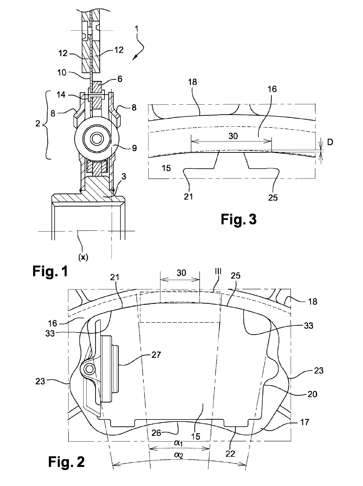
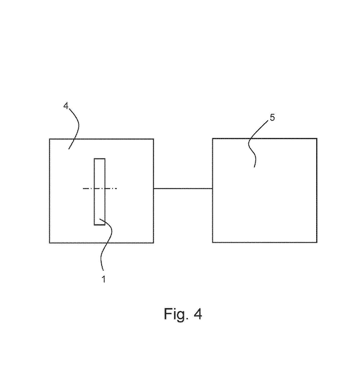
[0056]FIGS. 1 and 4 depict a friction disk 1 provided for a clutch 4 and equipped with a torsional damper 2 according to an exemplifying embodiment of the invention. This friction disk 1 comprises a hub 3 extending along an axis X. The hub 3 is installed, for example, on a region of an input shaft of a gearbox 5 and is rotationally integral with the input shaft thereof, as shown in FIG. 4.

[0057]In known fashion, damper 2 comprises an input element 6 and an output element 8 between which is interposed an elastic return member 9, the latter allowing a limited rotational displacement between the input element 6 and the output element 8. In the example described, the input element 6 is constituted by a web rigidly (i.e., non-moveably) coupled to a support disk 10 for friction linings 12. The support disk 10 constitutes an additional element for damper 2. The web 6 is rigidly (i.e., non-moveably) coupled to the support disk 10, for example, with the aid of rivets 14.

[0058]As is evident ...


PUM


Abstract

A torsional damper for vehicle transmission systems comprises an input element rotationally movable around an axis and exhibiting at least one window comprising two angularly spaced lateral edges and a radially external edge. An output element is rotationally movable around the axis and exhibits at least one window comprising two angularly spaced lateral edges and a radially external edge. An elastic return member capable of being received simultaneously in the window of the input element and the window of the output element generates a force acting against rotation of the output element with respect to the input element. An additional element is rotationally movable around the axis and integral with one of the input element and output element. The additional element exhibits an edge comprising at least one region projecting radially into the window of the input element and output element with which the additional element is integral.

Description

CROSS-REFERENCE TO RELATED APPLICATIONS AND CLAIM TO PRIORITY[0001]This application is a national stage application of International Application No. PCT / FR2015 / 051693 filed Jun. 24, 2015, which claims priority to French Patent Application No. 1456420 filed Jul. 4, 2014, the disclosures of which are incorporated herein by reference and to which priority is claimed.FIELD OF THE INVENTION[0002]The present invention relates to a torsional damper for a vehicle transmission system.[0003]The invention is applicable in particular, but not exclusively, to so-called “industrial” vehicles, the latter being, for example, trucks, public transit vehicles, or agricultural vehicles.BACKGROUND OF THE INVENTION[0004]In order to improve the filtering performance of a torsional damper, one can opt to use longer and wider springs and to arrange them along longer installation radii in windows of the damper. In the case in which that damper is integrated into a friction disk for a clutch, the springs gene...

Claims


Application Information

Patent Timeline
Patent Type & Authority Patents(United States)
IPC IPC(8): F16D13/68F16F15/123
CPCF16D13/686F16F15/1234F16D2300/22
Inventor MALLEY, MATTHIEUNERRIERE, ADRIEN
Owner VALEO EMBRAYAGES SAS
Why Eureka
Try Eureka