
Interface card socket

Inactive Publication Date: 2005-12-08
SUYIN CORPORATION
View PDF6 Cites 0 Cited by
  • Summary
  • Abstract
  • Description
  • Claims
  • Application Information

AI Technical Summary

Benefits of technology

[0007] The main objective of the present invention is to provide an interface card socket that has a strong uniform structure and can save material and time when manufacturing the interface card socket.
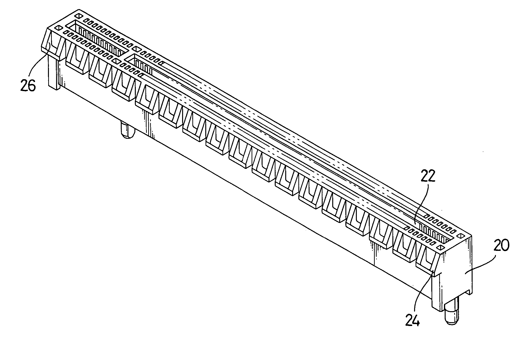
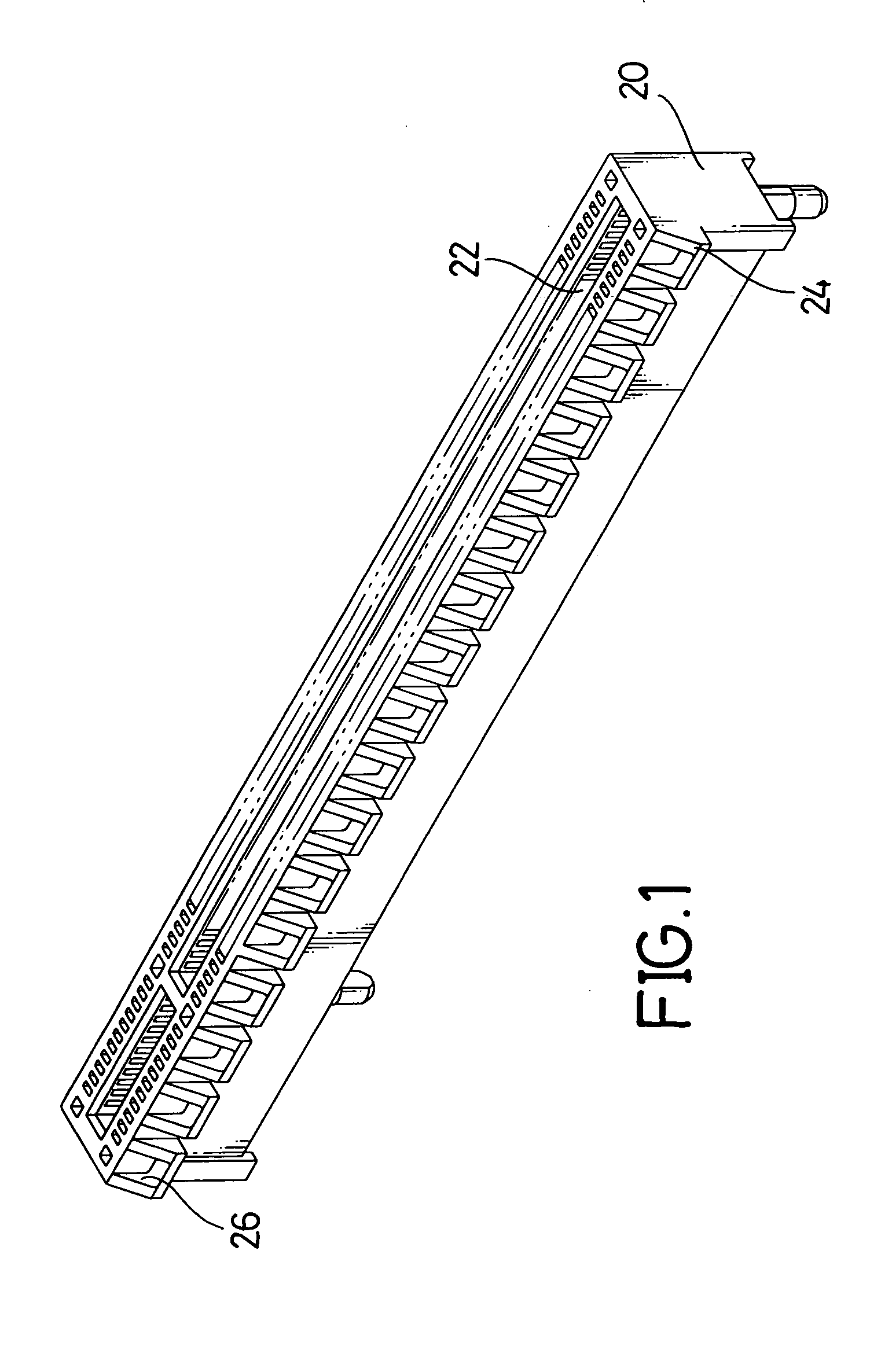
[0008] To achieve the objective, an interface card socket in accordance with the present invention comprises a body, multiple slots, multiple protruding hooks and multiple notches. The body has a top, a bottom, two sides and a middle. The bottom of the body is mounted on a motherboard of a computer. The multiple slots are formed in the middle of the body and open in the top of the body. The multiple protruding hooks are formed integrally with and extend out from one side of the body. The multiple notches are formed respectively in the corresponding protruding hooks. The interface card socket will save material, time and expense during the manufacturing process, and the structure is stronger than the conventional interface card socket.

Problems solved by technology

However, holding the interface card on the motherboard only depends on the strength of the interface card socket slot and the structure of conventional interface card sockets is often insufficient to maintain a viable connection over extended use.
The joint seam in the side of the interface card socket with the protruding hooks (14) will adversely affect the structural strength of the interface card socket and cause the interface card socket to easily break at the seam.

Method used


Image

  • Interface card socket
  • Interface card socket
  • Interface card socket

Examples


Embodiment Construction

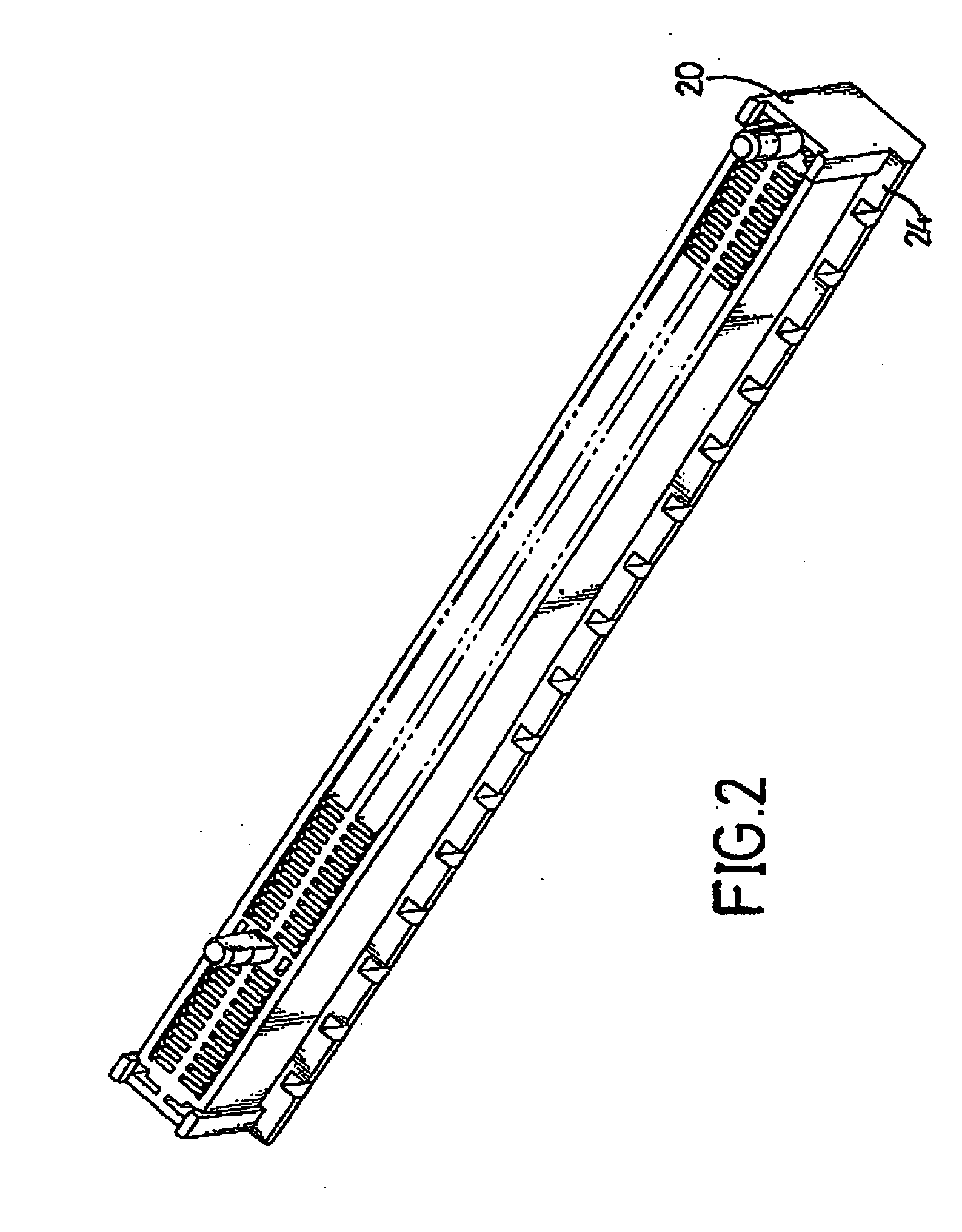
[0015] With reference to FIGS. 1 to 3, an interface card socket in accordance with the present invention comprises a body (20), multiple slots (22), multiple protruding hooks (24) and multiple notches (26). The body (20) has a top (not numbered), a bottom (not numbered), two sides (not numbered) and a middle (not numbered). The bottom of the body (20) is mounted on a motherboard of a computer (not shown). The multiple slots (22) are formed in the middle of the body (20) and open to the top of the body (20). The multiple protruding hooks (24) are formed integrally with and extend from one side of the body (20). Preferably, the cross sectional side of the protruding hooks (24) is triangular. The multiple notches (26) are formed respectively in the protruding hooks (24). Preferably, the cross sectional side of the notches (26) is triangular.

[0016] Since the interface card socket has a notch (26) in each protruding hook (24), the amount of material needed to manufacture the interface c...


PUM


Abstract

An interface card socket has a body, multiple slots, multiple protruding hooks and multiple notches. The body has a top, a bottom, two sides and a middle. The multiple slots are formed in the middle of the body and open to the top of the body. The multiple protruding hooks are formed integrally with and extend out from one side of the body. The multiple notches are formed respectively in the protruding hooks. The interface card socket will save material, time and expense during manufacturing, and the structure is strong.

Description

BACKGROUND OF THE INVENTION [0001] 1. Field of the Invention [0002] The present invention relates to an interface card socket, and more particularly to an interface card socket that has increased structural strength, is mounted in a motherboard of a computer and into which an interface card plugs. [0003] 2. Description of Related Art [0004] To increase the capability of a computer, a computer motherboard has multiple interface card sockets into which various interface cards with different functions plug. A conventional interface card socket has a slot and is mounted on the motherboard. The interface card can plug into the slot to connect to the motherboard. However, holding the interface card on the motherboard only depends on the strength of the interface card socket slot and the structure of conventional interface card sockets is often insufficient to maintain a viable connection over extended use. To solve this problem, Intel Corporation invented a new type interface card, and a ...

Claims


Application Information

Patent Timeline
IPC IPC(8): H01R43/18H01R12/16H01R13/62
CPCH01R43/18H01R12/85
Inventor HUANG, HUANG-CHOU
Owner SUYIN CORPORATION
Learn More